
Axial flux motors (AFMs) have surged from research labs into real products—from robotics and e-mobility to aerospace and distributed generation. Their disc-like geometry packs high torque in a short axial length, enabling thin, pancake-style machines that fit where traditional cylindrical (“radial flux”) motors struggle.
What is an Axial Flux Motor?
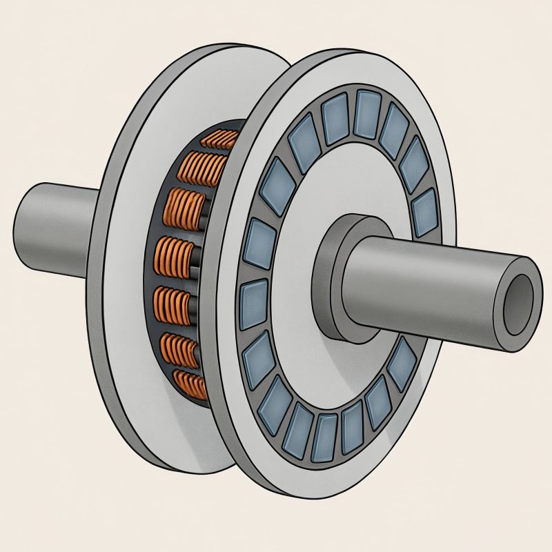
In an axial flux machine, magnetic flux travels parallel to the shaft (axially) across a flat air gap between a rotor disc with permanent magnets (or a wound field) and a flat stator disc with windings. By contrast, radial flux machines guide flux radially, across a cylindrical air gap between an inner rotor and outer stator. The axial configuration creates a large effective lever arm (mean radius), so for a given air-gap shear stress the torque scales roughly with the cube of radius and only linearly with axial length. That’s why AFMs tend to offer excellent torque density for a given mass and especially for limited axial space.
Common AFM topologies
- Single-stator, single-rotor (SS-SR): Simplest build; unbalanced axial magnetic forces must be handled structurally.
- Double-rotor, single-stator (DR-SS): Rotors on both sides of one stator balance axial forces and double the active area for the same diameter.
- Double-stator, single-rotor (DS-SR): A central rotor sandwiched by two stators; also balances axial forces and doubles active copper.
- Yokeless and segmented armature (YASA-type): Segmented tooth modules without a continuous back iron reduce iron mass and eddy losses, thereby improving torque density.
- Coreless (air-core) stator: Eliminates iron teeth to remove cogging and iron losses virtually; great for smoothness and partial-load efficiency, but lower flux density and higher copper mass.
- PCB stator (very low power): Spiral copper traces on FR-4 or polyimide; exceptional thinness and precision for fans/micro-drives at low torque.
Why Choose (or Not Choose) an AFM?
Strengths
- High torque density at modest diameter; thin “pancake” packaging with short axial length.
- Low cogging potential (especially with coreless or yokeless designs), yielding smooth motion and low acoustic noise.
- Scalability in disc area: Large-diameter, low-speed direct-drive generators/motors (e.g., wind, flywheels, test benches).
- Short end-turns with concentrated windings (in many AFMs) reduce copper loss.
Limitations
- Tighter air-gap control required: the flat faces must remain parallel under load and temperature.
- Thermal paths can be tricky: Large, thin discs need thoughtful heat extraction to avoid hot spots.
- Higher pole counts lead to higher electrical frequency at a given rpm (impacts inverter and losses).
- Manufacturing complexity for segmented stators, magnet fixtures, and rotor banding—especially at high rpm.
Typical Performance Ranges (Indicative)
Real performance depends on materials, cooling, control, duty cycle, and safety margins. The following ranges are conservative but useful for initial screening:
- Peak air-gap flux density (NdFeB): 0.6–0.9 T (teethed), 0.3–0.5 T (coreless)
- Specific electric loading (A, RMS): 20–60 kA/m (air-cooled), up to ~80 kA/m (aggressive liquid cooling)
- Continuous torque density: ~8–25 N·m/kg (well-cooled designs); peak can exceed 30–60 N·m/kg for short bursts
- Continuous power density: ~1–3 kW/kg; peak ~2–6 kW/kg (brief)
- Peak efficiency: 92–97% (properly optimized)
- Air gap: 0.3–1.5 mm typical (smaller at lower diameter/lower runout)
- Pole pairs: 6–40 (higher for large diameters/low speed)
These are not hard limits; specialized designs, advanced cooling (spray/oil jet, cold plates), and premium magnets can exceed them.
Losses and Efficiency
- Copper (I²R) losses: Dominant at high torque. Reduce via larger conductor cross-section, lower winding temperature, and higher fill factor (35–55% is typical with round or rectangular wire).
- Iron losses (hysteresis + eddy): Significant in teethed stators; reduce via thin laminations (0.1–0.35 mm), low-loss grades, or Soft Magnetic Composites (SMC) in 3D flux regions.
- Proximity & skin effect: Grow with electrical frequency and conductor geometry; mitigated by litz wire (low-power) or shaped bar conductors (higher power).
- Mechanical & windage: Rotating discs can incur windage; shrouding and smooth surfaces help.
- Inverter (switching + conduction) losses: Rise with electrical frequency (which rises with pole count at a given rpm). Correct device choice (SiC/MOSFET/IGBT), optimal PWM, and appropriate switching frequency are key.
Thermal Management
AFMs are thin and wide, so heat must be moved radially and axially out of copper and iron:
Conduction paths: From teeth/tooth-coils to back-iron to housing; or directly from slot/coil to a liquid-cooled plate.
Cooling options:
- Air convection over stator faces, with finned housings
- Liquid cold plates behind the stator
- Spray/oil-jet cooling directly on windings (advanced)
Heat flux ballparks: ~5–15 kW/m² (forced air), ~30–100 kW/m² (liquid plates), and higher for direct oil impingement with careful insulation.
Materials and Manufacturing
Magnets
- NdFeB (N42–N52, H/EH grades): Highest energy density; watch max temperature (80–180 °C depending on grade).
- SmCo: Lower remanence but far better thermal stability (200–300 °C); excellent for high-temp or demag-robust designs.
- Ferrite: Cheap and stable but low energy density; viable with flux concentration structures.
Stator iron
Electrical steel laminations (0.1–0.35 mm) for teethed stators; SMC for complex 3D flux; or none for coreless.
Windings
Round-wire coils, rectangular “hairpin-style” (less common in AFM but possible), or litz for high frequency/small machines.
PCB windings for micro-AFMs at low torque.
Rotor integrity
Magnets bonded to a steel or composite carrier; at higher rpm use non-magnetic banding (e.g., carbon fiber sleeves) to contain hoop stress and prevent magnet throw.
Tolerances
Flatness and parallelism matter. Air-gap uniformity within tens of microns improves efficiency and lowers acoustic noise.
Dynamic balance typically to ISO 21940 G2.5 (or better) for quiet operation.
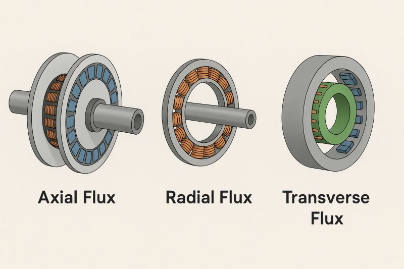
AFM vs Radial Flux vs Transverse Flux
Below is a practical comparison. Values are indicative—not absolutes—and assume competent cooling and modern materials.
| Attribute | Axial Flux (AFM) | Radial Flux (RFM) | Transverse Flux (TFM) |
| Packaging | Thin “pancake”, short axial length | Longer axial length, smaller diameter | Bulky, complex magnetic paths |
| Continuous torque density | High (8–25 N·m/kg, higher with liquid cooling) | Moderate–High (6–20 N·m/kg) | Potentially very high but hard to realize |
| Power density | 1–3 kW/kg (cont.), 2–6 kW/kg (peak) | 1–2.5 kW/kg (cont.), up to ~4 kW/kg (peak) | High potential; complex manufacturing |
| Pole count (typ.) | Medium–High (6–40 pairs) | Low–Medium (3–12 pairs) | High |
| Electrical frequency at given rpm | Higher (due to more poles) | Lower | Higher |
| Cogging & ripple | Very low with coreless/yokeless | Low–moderate (mitigation required) | Depends on design; often challenging |
| Cooling | Needs careful planar heat paths | Well-understood radial paths | Complex |
| Manufacturing difficulty | Moderate–High (discs, banding, precision) | Mature supply chains | High (3D flux paths) |
| Best fit | High torque in tight axial space; direct drive | General-purpose; wide speed range | Niche high-torque, low-speed applications |
Quick Sizing by Shear Stress
A fast way to estimate AFM diameter is to assume a tangential air-gap shear stress and a ratio between inner and outer radii. For many AFMs, the continuous shear stress falls around 20–40 kPa with good air- or liquid-cooling (peaks can be higher briefly).
| Rated Power | Speed (rpm) | Torque (N·m) | Suggested ror_o (m) | Outer Ø (m) | Electrical Frequency* (Hz) |
| 5 kW | 1500 | 31.83 | 0.0833 | 0.167 | 500 |
| 10 kW | 3000 | 31.83 | 0.0833 | 0.167 | 1000 |
| 25 kW | 3000 | 79.58 | 0.1131 | 0.226 | 1000 |
| 50 kW | 3000 | 159.15 | 0.1425 | 0.285 | 1000 |
| 100 kW | 3000 | 318.31 | 0.1796 | 0.360 | 1000 |
| 25 kW | 1000 | 238.73 | 0.1631 | 0.326 | 333 |
| 50 kW | 1000 | 477.46 | 0.2056 | 0.411 | 333 |
| 100 kW | 1000 | 954.93 | 0.2590 | 0.518 | 333 |
Key Design Parameters and Practical Ranges
Air gap
- 0.3–1.5 mm is common. Larger diameters and higher speeds push you to larger gaps for safety; precision machining and stiff structures let you shrink it.
Magnet thickness & pattern
- 2–6% of outer diameter as a loose starting point for medium sizes.
- Halbach arrays boost air-gap flux and reduce back-iron needs but add complexity.
Slot/pole combinations
- Fractional-slot concentrated windings (e.g., 12-slot/10-pole, 24-slot/22-pole, etc.) reduce end-turn copper and cogging.
- Ensure least common multiple (LCM) of slots and poles supports balanced three-phase windings and acceptable space harmonics.
Current density (in copper)
- 3–6 A/mm² RMS for air-cooled continuous, up to ~10 A/mm² (or more) with top-tier liquid cooling.
- Watch hot-spot temperature at tooth roots and the middle of thick coils.
Mechanical integrity
- Verify rotor hoop stress at max speed (typ. test at 120–150% of rated).
- Use non-magnetic sleeves (carbon fiber) to retain magnets at high rpm.
NVH (noise, vibration, harshness)
- Reduce cogging via magnet skew, tooth chamfering, fractional slot/pole, and coreless designs.
- Balance statically and dynamically; aim for low radial/axial pulsations in electromagnetic forces.
Materials Selection
| Component | Option | Pros | Cons | Notes |
| Magnets | NdFeB (N42–N52, H/EH) | Highest energy density; compact | Demagnetization at high temp; price volatility | Verify B HmaxB\!H_{max}BHmax, HciH_{ci}Hci; pick grade for thermal headroom |
| SmCo | High temp stability; corrosion-resistant | Lower energy; cost | Great for >180 °C operation | |
| Ferrite | Cheap; stable | Large volume; low flux | Works with flux concentration topologies | |
| Stator | Laminated steel (0.1–0.35 mm) | Mature; good loss control | 2D lamination constraints | Pick low-loss grades for high frequency |
| SMC | 3D flux capability | Lower permeability; higher loss at low freq | Useful for segmented teeth/yokeless | |
| Coreless (no iron) | Near-zero cogging; low iron loss | Lower flux density; more copper | Excellent smoothness/precision | |
| Windings | Round wire | Flexible, easy | Lower fill than rectangular | Good for prototypes and many series builds |
| Rectangular/bar | Higher fill, better thermal contact | Tighter bends; process control | Consider for >10 kW machines | |
| Litz | Reduces skin/proximity losses | Costly; sizing complexity | Suits high freq, small machines |
Control and Inverter Considerations
Field-Oriented Control (FOC) with sinusoidal commutation is standard. Concentrated windings introduce space harmonics; good current controllers and filtering mitigate torque ripple.
Electrical frequency rises with pole count: fe=p⋅rpm/6 High fe increases core/switching losses; SiC MOSFET inverters help at higher voltages/frequencies.
Back-EMF shape (trapezoidal vs sinusoidal) depends on slot/pole and magnet shaping; sinusoidal reduces ripple and acoustic noise.
Sensoring: Encoders or resolvers for high dynamic performance; sensorless FOC possible but harder at low speed.
DC link & filtering: With high pole counts, ensure adequate DC-link capacitance and consider dv/dt on windings (partial discharge risk at high voltage).
Application Snapshots
- E-Mobility (e-motorcycles, light EVs, AGVs): Thin form factor frees up packaging; high torque at wheel speed; watch thermal management in sealed housings.
- Aerospace/eVTOL: High torque density and smoothness are attractive; materials must meet stringent temperature and reliability requirements; SmCo may be favored.
- Robotics/Co-bots: Coreless AFMs excel where ultra-smooth, low-cogging torque and back-drivability matter.
- Wind & direct-drive generators: Very large-diameter axial flux alternators at low rpm; ferrite or NdFeB with flux concentration to manage cost.
- Industrial spindles & test rigs: Thin profile allows direct-drive torque at modest speed without gearboxes, reducing backlash and maintenance.
Integration Tips (What Often Gets Missed)
- Axial force balance: Favor DR-SS or DS-SR to cancel magnetic attraction; it relaxes bearing selection and housing stiffness.
- Runout and flatness: Measure it hot. Composite rotors and aluminum housings expand differently; keep the gap safe at max temperature and max rpm.
- EMC & cabling: High pole counts/electrical frequencies raise dv/dt stress; choose proper cable shielding and winding insulation class.
- Magnet retention & safety: Design for overspeed and thermal excursions; potting and sleeves must block magnet lift-off.
- Serviceability: Segmented stator teeth and modular rotors reduce downtime for coil/PM replacement.
- Thermal sensors: Bury RTDs/NTCs near tooth roots and middle of dense coils to catch hot spots early.
- Cost realism: Premium magnets and tight machining tolerances dominate BOM; early DFM with your supplier avoids last-minute cost creep.
Axial flux motors win when the envelope demands high torque in minimal axial length and when smoothness, compactness, and modularity matter. To realize that promise, you must nail air-gap control, thermal paths, and inverter matching, and select materials that fit your temperature and cost realities. Use the shear-stress sizing shortcut to get in the right diameter ballpark, pick a topology (DR-SS and DS-SR are workhorses), and iterate with your supplier on cooling and manufacturability. With sound engineering, AFMs deliver standout torque density and refined operation across e-mobility, aerospace, robotics, and direct-drive generation.