





-
Home Appliance Market
Committed to providing innovative solutions for the global home appliance industry
- Leading brand in global air conditioning sweep motor market
- A global leader in washing machine drainage systems
- Global Refrigerator lce Water System Solution Provider
Home Appliance Market
Committed to providing innovative solutions for the global home appliance industry
- Customer Cases




- Specific Classfication
 Air Conditioner
 Refrigerator
 Washing Machine
 Kitchen & Bathroom
 Small Home Appliances
-
Auto Parts
Provide motor and mechatronic components for automobiles
- Product advantages of stepper motors for HUD
- Large-scale automotive water pump production capacity
- Automotive air conditioning system solution capabilities
Auto Parts
Provide motor and mechatronic components for automobiles
- Customer Cases




- Specific Classfication
- Air Conditioning System
 Thermal Management
 Intelligent Driving
 Intake & Exhaust System
 Body Control
 Braking System
-
Industrial Control
Provide cost-effective motor and component products in the industrial field
- First-tier brand suppliers in the valve control market
- Domestic security monitoring head enterprise supplier
- Multiple series of products meet different application scenarios
Industrial Control
Provide cost-effective motor and component products in the industrial field
- Customer Cases




- Specific Classfication
 Valve Control
 OA Finances
 Garden Tools
 Industrial Equipment
 Security Monitoring
 Robot
Robot
-
Sports Health
Provide high-quality motors for sports equipment and medical equipment industries
- High-end sports equipment main drive motor supplier
- First-tier brand suppliers in the medical device industry
- Ability to provide solutions such as smart furniture
Sports Health
Provide high-quality motors for sports equipment and medical equipment industries
- Customer Cases




- Specific Classfication
 Sports Equipment
 Medical Instruments
 Game Entertainment
 Smart Home
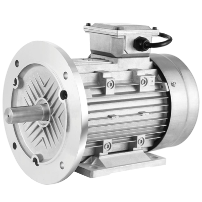
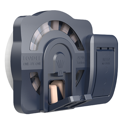
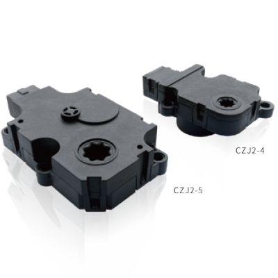




Jiangsu Leili will participate in the 2026 (19th) Beijing International Automotive Exhibition, one of the most influential events in the automotive industry. Through this exhibition, Leili will present its latest products, technologies, and application solutions, while strengthening communication with industry partners and customers from across the automotive supply chain.
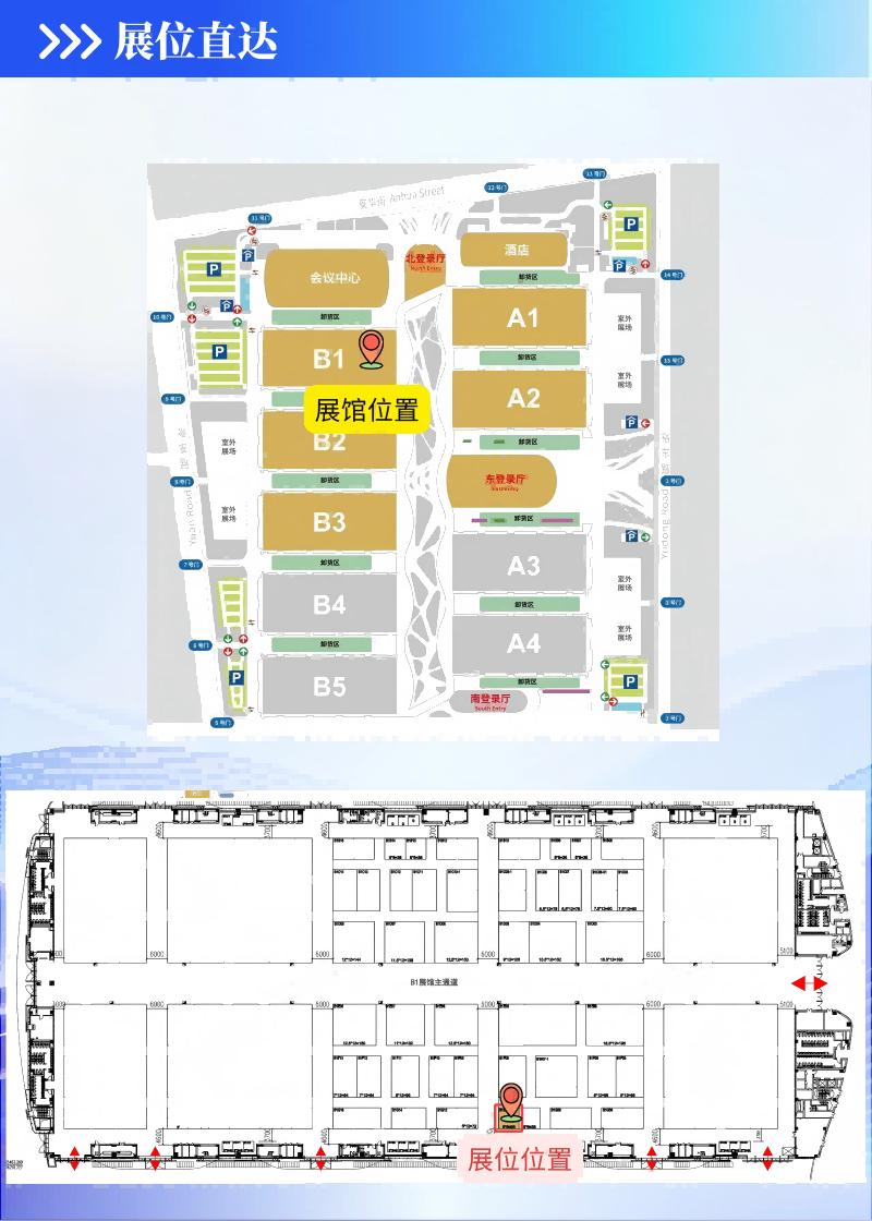
The exhibition will be held from April 24 to May 3, 2026 at the Capital International Exhibition Center in Beijing. According to the event schedule, April 24–25 will be Media Days, April 26–27 will be Trade Visitor Days, and April 28–May 3 will be open as Public Days. During the exhibition, Leili will welcome visitors at Booth B1G10.
As a company focused on motor and related technology solutions, Leili will use this platform to demonstrate its brand strength, product innovation, and industry application capabilities in the automotive sector. The booth design highlights a modern and professional brand image, creating a clear and engaging space for product display, technical communication, and business discussions.
The Beijing International Automotive Exhibition is an important opportunity for enterprises across the automotive industry to showcase innovation, explore cooperation, and stay connected with market trends. By participating in this event, Leili aims to further enhance its industry visibility, expand business opportunities, and build closer relationships with customers and partners.
We sincerely invite industry professionals, partners, and visitors to stop by Leili Booth B1G10 and learn more about the company’s latest developments and automotive-related solutions.
Exhibition Information
Event: 2026 (19th) Beijing International Automotive Exhibition
Dates: April 24 – May 3, 2026
Venue: Capital International Exhibition Center, Beijing
Booth No.: B1G10
Exhibitor: Jiangsu Leili
Choosing between a single-stage and multi-stage geared stepper requires more than comparing reduction ratios. Gear layout affects transmission losses, package dimensions, backlash, and the torque available under real operating conditions.
Useful comparisons hold total ratio and output duty constant, then assess each gearbox at its actual speed, load, temperature, and lubrication condition.
What Defines Single-Stage and Multi-Stage Gearboxes?
A gear stage is one meshing or transmitting reduction set between an input and output member. A single-stage gearbox achieves reduction through one gear set, whereas a multi-stage design transmits motion through successive reduction sets.
Determine an individual stage’s ratio by dividing its rotational input speed by its rotational output speed. In a compound gearbox, the overall reduction ratio is the product of its individual stage ratios.
Written plainly, total ratio = stage ratio 1 × stage ratio 2 × … × stage ratio n. The ratios multiply; they are not added.
To illustrate, a hypothetical 12:1 total reduction could use one 12:1 stage, two stages of 3:1 and 4:1, or three stages of 2:1, 2:1, and 3:1.
These ratios are arithmetic examples only, not claims that every arrangement is practical within a particular gearbox type, size, or operating envelope.
The same total ratio can provide the same nominal output speed from a given input speed, but internal gear speeds, tooth loads, bearing loads, and packaging may differ.
Those differences influence efficiency, temperature, wear, and the available housing envelope, so stage count should be considered alongside the actual transmission architecture.
When evaluating a geared stepper, start with required output torque, speed, movement profile, and holding condition. Then compare gearbox architectures capable of meeting those requirements.
Leili Motor’s geared stepper motor range is a useful starting point for an initial technical review of integrated motor-and-gearbox configurations.
How Do Gearbox Losses Change with Configuration?
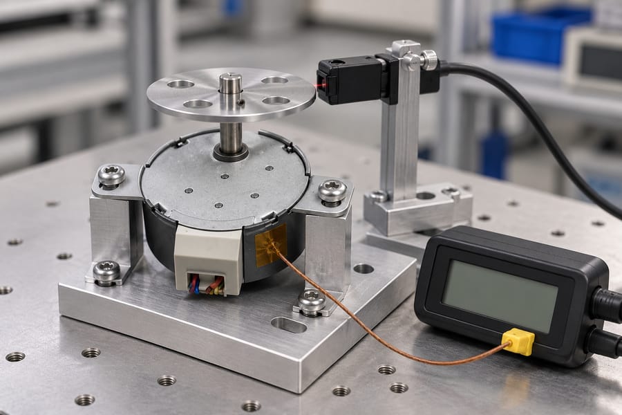
Gearbox losses arise from gear-mesh friction, bearing friction, seal drag, and lubricant churning. Their relative contributions depend on gear type, geometry, material, lubrication, temperature, speed, load, and assembly details.
A stage adds interfaces and rotating components, but that alone does not establish a universal efficiency ranking. A well-designed multi-stage arrangement may use favorable ratios at each stage.
Conversely, a single high-ratio stage may require geometry that produces different contact, bearing, or lubrication losses. Compare complete designs rather than inferring performance from stage count alone.
For a first-order estimate, multiply the efficiencies of individual stages, provided each value applies at the relevant operating point. With two stages, overall efficiency = stage 1 efficiency × stage 2 efficiency.
For three stages, overall efficiency = stage 1 efficiency × stage 2 efficiency × stage 3 efficiency. This product estimates gearbox transmission efficiency, not motor-drive system efficiency.
The following numbers are deliberately hypothetical arithmetic examples, not Leili Motor product data, measured results, or general efficiency expectations. All arrangements assume the same total ratio and output duty.
Specifically, the example assumes a 12:1 ratio, 300 rpm input, 25 rpm output, and 0.5 N·m output torque. Each stage efficiency is stipulated solely for illustration.
| Hypothetical arrangement | Assumed stage efficiencies | Overall gearbox efficiency |
| One 12:1 stage | 92% | 92.00% |
| 3:1 × 4:1 stages | 96% × 96% | 92.16% |
| 2:1 × 2:1 × 3:1 stages | 97% × 97% × 97% | 91.27% |
The table demonstrates the multiplication method, not a design rule. Actual per-stage efficiencies require measurements or applicable engineering data; the assumed values cannot predict the best layout.
Keep gearbox shaft efficiency separate from electrical-input system efficiency. Gearbox shaft efficiency = mechanical output power at the gearbox shaft ÷ mechanical input power at the gearbox input shaft.
Electrical-input system efficiency = mechanical output power at the gearbox shaft ÷ electrical power drawn by the motor-drive system. This broader figure includes motor and drive losses.
Mechanical shaft power = torque × angular speed. At zero output speed, output mechanical power is zero even if the gearbox resists a load, so the power ratio is not a useful motion-efficiency rating.
Evaluate holding torque, backdriving behavior, and power-off load retention separately. Static holding concerns resisting movement, not conversion of input power into useful rotating output.
Fixed losses can represent a larger share of transmitted power when the gearbox carries a light load. Mesh and bearing losses may not fall proportionally with output load.
Consequently, the percentage of input power lost may rise at low load even when absolute losses change little. This is a fractional effect, not necessarily a sudden deterioration in hardware.
Churning losses often increase with rotational speed because moving parts agitate lubricant more vigorously. The exact trend depends on lubricant viscosity, fill level or grease distribution, clearances, and gearbox design.
Do not assume one universal speed-loss curve. Evaluate representative operating points, because lubrication choices and internal geometry can change how losses develop as speed rises.
Evaluate each candidate over the full application duty cycle, covering representative operating conditions rather than relying on a single rated point. Include starts, stops, sustained running, load changes, and thermal stabilization where relevant.
Efficiency and temperature can differ between transient and steady operation, so record test conditions with each result. This makes comparisons traceable and prevents unlike measurements from being treated as equivalent.
How Do Stage Count and Packaging Affect Size?
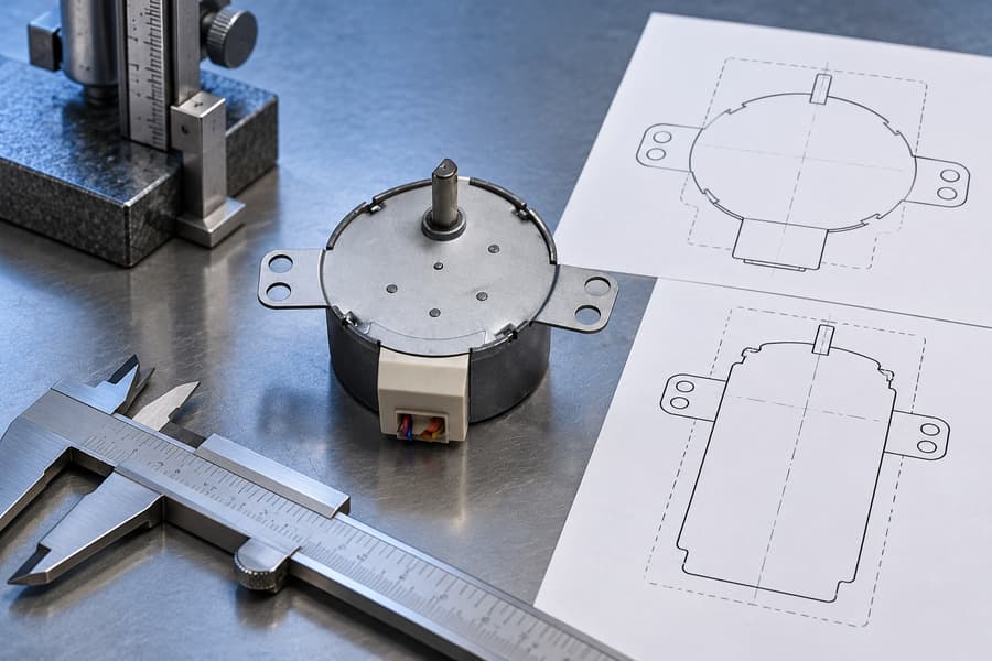
Stage count changes how reduction is distributed through the gearbox, but it does not determine the envelope alone. Gear type, stage ratios, center distance, bearings, and housing design all matter.
A single high-ratio stage may need a larger gear diameter or greater center distance to achieve the reduction within acceptable tooth geometry and loading. This can increase radial dimensions.
A multi-stage layout can divide the total ratio across smaller gear sets, potentially reducing the largest gear diameter. The trade-off is added shafts, bearings, meshes, and spacing that may extend axial length.
This is not a universal size advantage. A multi-stage arrangement may fit a narrow diameter limit but exceed available length; another design may fit a wider, shallower housing.
Ask how the ratio is divided across stages and which stage carries the highest speed and torque. These details influence tooth loading, bearing selection, lubricant behavior, and heat.
Ask for the full envelope drawing, not only gearbox diameter or face dimensions. Check overall length, mounting features, shaft projection, connector access, and installation or removal space.
Center distance matters when the gearbox connects to belts, pulleys, couplings, or driven mechanisms. A gearbox may fit the motor footprint yet create awkward transmission geometry or interfere with nearby parts.
Output bearing support matters when the driven load applies radial or axial forces. Confirm permitted bearing loads and the conditions behind each rating, including load direction and speed.
An overhung pulley or coupling applies force away from the bearing support. Greater offset can raise bending moment and bearing stress, so check load position alongside output torque.
Housing stiffness, shaft support, lubrication, and sealing also affect packaging. Extra stages may need additional bearing locations, while a large single-stage gear may require more radial clearance.
Check whether the gearbox can be mounted in the intended orientation without changing lubrication performance. A compact drawing is insufficient if oil level or grease distribution depends on orientation.
Service access is part of the usable size. Leave room for mounting screws, cable routing, inspection, lubricant service where applicable, and removal without dismantling unrelated equipment.
Compare the complete installed envelope, including motor, gearbox, connectors, coupling, and maintenance clearance. Nominal gearbox dimensions alone cannot establish whether the assembly fits and remains serviceable.
How Should Buyers Compare Equivalent Configurations?
Start with one common operating requirement for every candidate. Specify total reduction ratio, output speed and torque, motion profile, load inertia, duty cycle, ambient conditions, and expected service life.
Do not compare one gearbox at efficient mid-load with another at low speed or near its load limit. Use equivalent application operating points and comparable thermal conditions.
For intermittent movement, describe acceleration, travel time, dwell, stopping frequency, and holding periods. For continuous operation, specify sustained speed and torque because heat and lubrication behavior can differ.
Ask whether rated output torque applies continuously, intermittently, or under a defined thermal condition. Also check whether speed, torque, and service-life ratings assume particular mounting and lubrication conditions.
Backlash comparisons need a common reference shaft. Stage angle values cannot simply be added when they describe different shafts, because each angle represents a different output displacement.
For an ideal ratio model, refer each stage’s angular contribution to the final output by dividing by the product of subsequent stage ratios. Combine contributions only after conversion to that same shaft.
Actual lost motion may also reflect tooth clearance, bearing clearance, shaft compliance, housing deflection, and measurement method. Request the supplier’s definition and test setup before comparing arcminutes.
The initial purchase price represents only part of the total ownership cost. Consider assembly complexity, lubrication requirements, expected wear, replacement access, downtime consequences, and the cost of maintaining output performance.
Additional stages introduce more components and interfaces, but component count alone does not establish reliability. Tooth loading, bearings, materials, lubrication, manufacturing quality, and environment can outweigh stage count.
Likewise, a single-stage design is not automatically cheaper or more robust. A large gear, specialized housing, or demanding tooth geometry may offset savings from fewer components.
Ask which failure modes matter: tooth wear, bearing fatigue, lubricant degradation, seal wear, overheating, or excessive lost motion. Then request evidence supporting the expected service interval under the proposed duty.
Request identical duty-cycle assumptions for life estimates, including starts per hour, reversals, shock loads, and daily operating time. Otherwise, quoted service lives may not be comparable.
Motor compatibility matters too. A gearbox changes required motor speed and torque, while available motor torque depends on speed and drive conditions.
Review motor and transmission together against the intended load profile. Leili Motor’s stepper motor range can help frame motor-side requirements alongside gearbox selection.
Before narrowing the shortlist, request comparable drawings, ratings, efficiency conditions, backlash definitions, allowable output loads, lubrication details, and service assumptions. Consistent evidence makes trade-offs easier to judge.
How Should Performance Be Validated?
A meaningful comparison requires both gearbox configurations to operate under equivalent output requirements. Define the total reduction ratio, output torque, speed profile, load, duty cycle, mounting orientation, and ambient conditions before testing.
Use the same application-representative operating points for both candidates. Where exact operating conditions cannot be reproduced, document the differences and avoid treating the resulting measurements as directly equivalent.
Measure Actual Shaft Torque and Speed
Measure mechanical input and output torque and rotational speed at the respective gearbox shafts. Record instrument locations, coupling arrangements, calibration status, and operating conditions for every measurement.
Calculate mechanical shaft power from measured torque and angular speed. When torque is expressed in newton-metres and angular speed in radians per second, the resulting power is expressed in watts.
Gearbox shaft efficiency equals output mechanical shaft power divided by input mechanical shaft power. This isolates gearbox transmission performance from losses occurring in the motor and drive.
Electrical-input system efficiency instead divides gearbox output mechanical power by the electrical power supplied to the motor-drive system. This broader measurement includes electrical, motor, and gearbox losses.
Keep the two efficiency figures separate in the acceptance report. If electrical-input efficiency is required, measure electrical power using a method appropriate to the drive waveform and operating conditions.
Account for Measurement Uncertainty and Operating Temperature
Low-power measurements require particular care because instrument offsets and measurement uncertainty may represent a substantial fraction of the measured power. Report uncertainty alongside calculated efficiency rather than overstating small differences.
At low output torque or speed, determine whether the measurement system can resolve the expected mechanical power accurately. If uncertainty overlaps the difference between candidates, report the comparison as inconclusive.
Run each candidate under the specified representative duty until the agreed temperature-stabilization criterion is met. Record gearbox housing temperature, ambient temperature, load, speed, and elapsed operating time.
Use consistent sensor locations and measurement procedures across candidates. Interpret housing temperature alongside the supplier’s applicable temperature ratings and lubrication requirements, not as a direct measurement of every internal component.
A gearbox that performs acceptably during brief movement may behave differently during sustained operation. Include continuous running, intermittent motion, or dwell periods only where they represent the intended application.
Verify Lost Motion, Bearing Loads, and Noise
Measure reversal lost motion using a defined procedure that applies controlled torque reversals and records corresponding output angular displacement. Keep the reference shaft, loading conditions, fixture arrangement, and measurement method consistent.
If input locking is used, specify how the input is restrained and whether the gearbox is tested unpowered or under another defined condition. Do not mix results obtained using different restraint methods.
Distinguish backlash from elastic deflection, fixture movement, and shaft compliance. Report the measurement method and uncertainty, and refer angular contributions to the same shaft before comparing multi-stage configurations.
Check output bearing loads against the supplier’s documented limits, considering radial and axial forces, load direction, and the actual distance between the applied load and bearing support.
Include noise measurements only when acoustic performance is an application requirement or specified rating. Define the measurement position, operating speed, load, background conditions, and applicable acceptance requirement beforehand.
Establish Comparable Acceptance Criteria
The following table provides a compact acceptance framework. Numerical limits should come from documented supplier ratings and application requirements, not assumed universal tolerances.
| Validation item | Measurement or test condition | Acceptance basis |
| Output performance | Measure shaft torque and speed at equivalent duty points | Required output duty and documented ratings |
| Gearbox efficiency | Calculate from mechanical input and output shaft power | Application-defined requirement, accounting for uncertainty |
| Electrical-input efficiency | Measure electrical input and mechanical gearbox output power | System-level requirement, reported separately |
| Temperature | Record temperatures after agreed stabilization under representative duty | Documented thermal limits and application requirements |
| Reversal lost motion | Apply defined torque reversals and measure output displacement | Specified backlash or lost-motion requirement |
| Output bearing loads | Check actual radial and axial loads, including overhang | Applicable supplier load ratings |
| Static holding | Evaluate resistance to movement under the specified holding condition | Required holding performance and documented limits |
| Noise, if specified | Measure under defined speed, load, and acoustic conditions | Agreed acoustic specification |
Static holding must be assessed separately from rotating efficiency. At zero output speed, mechanical output power is zero, so an input-to-output power ratio does not provide a meaningful motion-efficiency rating.
Do not introduce holding loads, temperatures, speeds, or other test conditions beyond documented ratings. Any additional qualification must be agreed with the supplier and confirmed safe for the selected configuration.
Document the Selected Configuration
Request supplier drawings, stage ratios, rated operating conditions, efficiency definitions, backlash specifications, bearing-load limits, lubrication instructions, and applicable temperature and service-life information.
Record the selected configuration, motor and gearbox identification, test equipment, calibration status, duty profile, environmental conditions, raw measurements, calculated results, uncertainty, and acceptance criteria.
The final acceptance record should identify the test procedure and revision, measured deviations, disposition of unresolved differences, and supplier approval. Retain sufficient evidence for another engineer to reproduce the comparison under the same conditions.
Single-shaft and double-shaft hybrid steppers share the same operating principle but provide different mechanical interfaces. Before selecting either configuration, OEM engineers should assess accessory needs, available mounting space, and future maintenance accessibility.
A rear shaft can accommodate additional components, but it introduces alignment, loading, and guarding considerations. Comparing complete assemblies helps engineers identify the arrangement that best supports equipment integration.
What Is the Difference Between Single-Shaft and Double-Shaft Hybrid Steppers?
Hybrid steppers achieve controlled movement in discrete angular increments through interacting permanent magnets and toothed magnetic components. Their shaft arrangement determines which mechanical interfaces are accessible for external connections.
The distinction concerns shaft accessibility rather than a fundamental change in stepping operation. Both configurations can be evaluated using the same basic electrical and mechanical selection principles.
Single-Shaft Hybrid Stepper Design
A single-shaft hybrid stepper provides one externally accessible shaft extension, generally used to transmit motion from the motor to the driven mechanism.
This arrangement can simplify rear-end packaging when the application does not require an external encoder, brake, or manually operated adjustment device.
However, a single-shaft configuration does not automatically exclude feedback or braking functions. Supplier-integrated assemblies may incorporate these features through alternative internal arrangements.
Engineers should confirm the actual shaft geometry, mounting surfaces, and available accessory options from the selected motor’s approved technical documentation.
Double-Shaft Hybrid Stepper Design
A double-shaft hybrid stepper provides accessible shaft extensions at opposite ends of the rotor assembly. Their dimensions and mechanical interfaces depend on the specific configuration.
Both extensions rotate together because they belong to the same rotor. They cannot provide independently controlled rotational speeds or positions.
Importantly, adding a second shaft extension does not double the motor’s available torque. Both ends share the electromagnetic torque produced by the motor.
When both ends transmit mechanical loads, their combined torque demand must remain within the motor’s available capability and applicable shaft-interface limits.
The rear extension may accommodate compatible accessories, although its presence alone does not establish that a particular encoder, brake, or coupling will fit.
Table 1: Single-Shaft vs Double-Shaft Hybrid Stepper Integration Comparison
| Integration Factor | Single-Shaft Configuration | Double-Shaft Configuration |
| Drive connection | One accessible shaft extension | Accessible extensions at both ends |
| Rear accessories | May require integrated alternatives | Can support compatible external accessories |
| Installation envelope | May reduce external rear-end requirements | Additional rear clearance may be necessary |
| Mechanical integration | Fewer accessible shaft interfaces | Additional coupling and alignment considerations |
| Rotating-part protection | Guard accessible drive components | Rear extension may require additional guarding |
| Maintenance access | Depends on assembly design | Rear accessory servicing may require access |
Neither arrangement guarantees simpler installation. The advantage depends on the complete mechanical assembly, accessory requirements, and available equipment space.
How Do Rear-Shaft Accessories Affect Motor Integration?
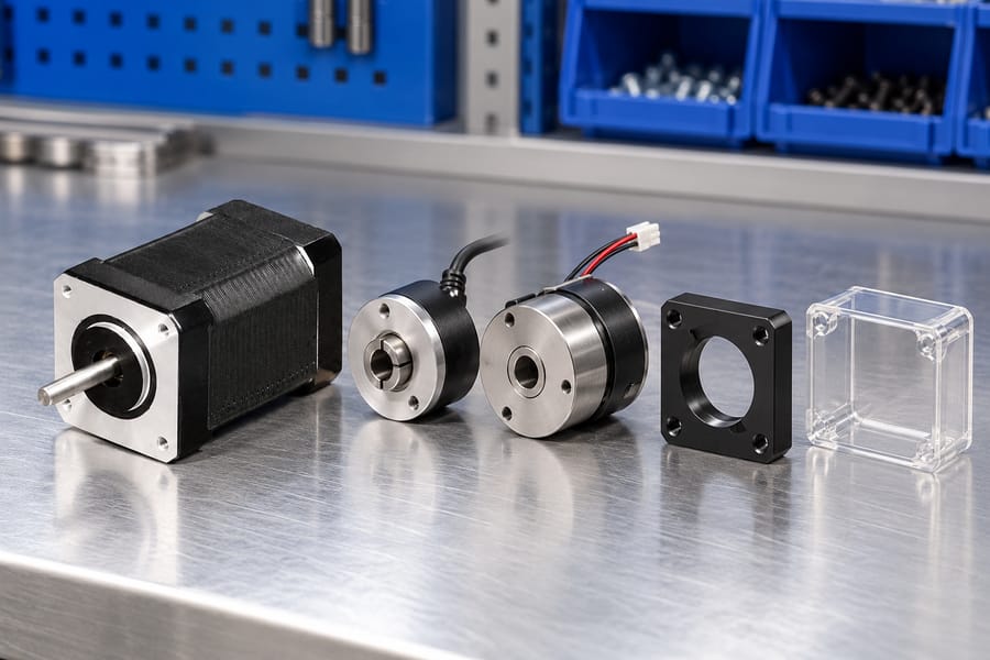
A rear extension can provide a convenient mechanical connection for auxiliary equipment. However, each accessory introduces specific mounting, operational, and maintenance requirements.
Rear-Shaft Encoder Installation
An encoder attached to the rear extension can measure rotor movement and provide position or speed information to a compatible controller.
Mechanical integration requires attention to shaft concentricity, coupling alignment, permissible runout, and encoder mounting stability. Excessive misalignment can compromise measurement reliability or damage components.
Encoder resolution alone does not determine positioning accuracy. Coupling behavior, motor movement, transmission errors, and the feedback control arrangement also influence measured performance.
Engineers should verify the encoder’s mounting interface and cable routing while ensuring sufficient access for inspection, adjustment, and eventual replacement.
Electromagnetic Holding Brake Integration
A rear-mounted electromagnetic brake can help retain shaft position when engaged, provided its holding capacity suits the actual load and transmission arrangement.
A brake intended for stationary load retention should not be assumed capable of stopping a moving mechanism. Permitted engagement speed, stopping energy, and operating frequency require separate verification.
Brake selection must also account for mounting alignment, engagement behavior, release timing, and the consequences of power loss under the intended operating conditions.
Where an application requires a safety-related stopping or holding function, engineers must separately establish whether the selected brake assembly and control architecture satisfy those requirements.
Manual Adjustment and Positioning
A rear extension may accommodate a manual adjustment knob for selected commissioning or maintenance operations, provided the shaft interface and machine design permit it.
Before manual adjustment, isolate electrical power and prevent unexpected movement. Secure gravity-driven loads and stored mechanical energy according to the equipment’s isolation procedure.
During powered operation, exposed rear shafts and attached knobs require suitable guarding to prevent accidental contact with rotating components.
External Accessories vs Integrated Assemblies
External encoders and brakes offer possible configuration flexibility, but they also require appropriate mounting structures, coupling interfaces, electrical connections, and installation clearance.
Supplier-integrated solutions may package accessories differently, potentially reducing external assembly work without necessarily retaining the same accessible rear-shaft arrangement.
For an appropriate starting point, review available hybrid stepper motor configurations and request drawings identifying the actual shaft and accessory interfaces.
Leili Motor configuration options should be assessed through confirmed specifications rather than assumptions about universal accessory compatibility, standardized dimensions, or interchangeable mounting arrangements.
What Shaft Loads and Mechanical Constraints Must Engineers Evaluate?
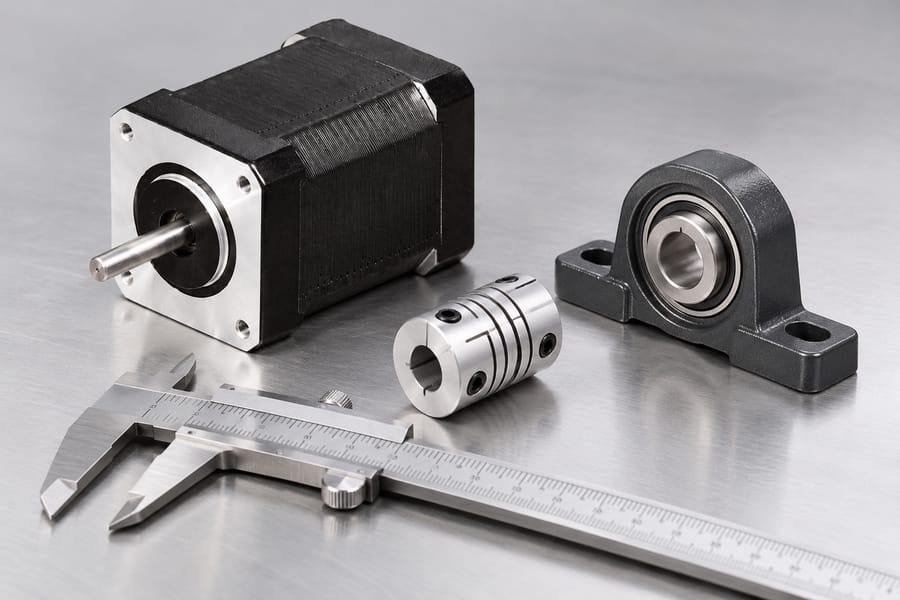
Torque Capacity at Each Shaft Extension
Both extensions transmit torque through one rotor assembly. The available motor torque depends on operating speed, drive settings, supply conditions, temperature, and the specified duty cycle.
When the front shaft drives a mechanism and the rear shaft drives an accessory, their simultaneous torque demands contribute to the same motor loading.
Check the allowable transmitted torque for each shaft extension and its coupling interface separately. A motor torque rating does not establish every shaft connection’s mechanical capacity.
Request supplier approval for the combined operating case, including acceleration, reversals, accessory drag, and transient loads rather than assuming the two ends have independent limits.
Radial, Axial, and Overhung Loads
A pulley, gear, or offset coupling can apply radial force to a shaft. Its bearing effect depends partly on the force’s distance from the support.
An attachment farther from its nearest bearing typically increases bending moment at that support. Record the applied force, its direction, and the effective lever arm.
Front and rear attachments can load common bearing structures simultaneously. Ask the supplier to evaluate combined reactions, not simply approve each extension in isolation.
Axial forces also require attention, particularly where screws, thrust-loaded couplings, or accessory mechanisms transfer forces along the shaft axis during operation.
Opposing axial forces should not be assumed to cancel harmlessly. Internal bearing arrangements, thermal movement, and changing load directions can alter the resulting reactions.
Confirm allowable radial and axial loads at their actual application points, together with any supplier restrictions on concurrent loading, operating speed, and service life.
Alignment, Couplings, and Brake Reactions
An encoder normally requires a stable reference between its body and the motor housing. Misalignment or mounting distortion can introduce unnecessary bearing and coupling loads.
Secure encoder cables so connector weight, routing tension, and incidental cable pulls do not act directly on the encoder body or rotating connection.
A rear brake also needs a reaction-torque path into suitable stationary structure. Its mounting fasteners and bracket must withstand specified holding or braking reactions.
Avoid connecting rigidly supported equipment to both shaft ends without examining alignment. Independent supports can overconstrain the rotor and increase bearing stress.
Flexible couplings can accommodate a defined amount of angular or parallel offset, but they do not justify disregarding alignment limits or accessory bearing requirements.
Verify mounting-face geometry, shaft runout, coupling engagement, and permissible movement across anticipated temperatures. Assess the complete installed assembly rather than individual components alone.
How Does Shaft Configuration Influence Installation Space and Maintenance?
Installed Envelope and Supporting Structure
Compare the complete assembled envelope, including rear attachments, brackets, connectors, guards, and cable exits. Motor-body length alone cannot represent the required machine space.
Leave space for operating cable bend radii and strain relief, especially when cables exit toward a nearby wall or moving machine structure.
The motor’s front flange normally locates and secures its housing to the machine. That mounting interface does not automatically increase permissible shaft-bearing loads.
Check flange contact, fastener engagement, mounting flatness, and structural rigidity against supplier drawings. Distorted mounting surfaces can undermine alignment and accessory operation.
Rear Access and Service Removal
An accessible rear shaft may simplify attachment during assembly but complicate removal after the machine is enclosed by panels, wiring, or adjacent equipment.
Provide clearance for disconnecting cables, withdrawing couplings, removing brake fasteners, and extracting an encoder without disturbing unrelated assemblies or damaging wiring.
Consider actual tool approach angles and replacement-part travel paths. Service clearance is different from the small gap needed merely to accommodate operating components.
Where rear access is impractical, compare an alternative accessory arrangement or an integrated assembly using approved installation drawings and documented maintenance procedures.
Guarding and Safe Manual Adjustment
Protect exposed rotating extensions, coupling hubs, and adjustment knobs during powered operation. Guards must suit the machine’s actual access points and operating environment.
Manual adjustment requires an isolated energy state, not merely a stopped motion command. Follow verified isolation procedures before approaching or turning a shaft.
Secure elevated axes and other hazardous loads against dropping, drifting, or unexpected backdriving. Account for springs, stored energy, and externally driven mechanisms.
An engaged holding brake should not replace independent load securing unless the validated safety design explicitly permits that approach under the specified maintenance conditions.
What Electrical and Driver Compatibility Checks Are Necessary?
Motor and Driver Matching
Shaft count does not independently determine winding compatibility. Check phase wiring, rated current conventions, winding characteristics, drive operating modes, and supply-voltage requirements.
Evaluate usable torque across the intended speed and acceleration profile with the actual driver. A mechanically compatible motor may still lack adequate dynamic margin.
Accessory Wiring and Control
For encoder installations, confirm supply requirements, signal format, connector pinout, and controller input compatibility. Route feedback cables to reduce mechanical strain and electrical interference.
For electromagnetic brakes, verify coil supply, switching protection, command sequencing, and release timing. Confirm that loss-of-power behavior matches the machine’s defined operating needs.
When Should OEMs Choose Single-Shaft or Double-Shaft Hybrid Steppers?
Start With the Actual Machine Interfaces
Begin by drawing the driven mechanism and identifying which shaft connections must remain accessible after installation. Mark power transmission, feedback, holding, and adjustment functions separately.
Identify whether each function truly needs a rotating rear extension. An encoder or brake requirement does not necessarily require an externally accessible double-shaft configuration.
Next, identify which components are installed during production and which must be replaced in service. An accessible interface offers little benefit if surrounding equipment blocks removal.
Compare Complete Candidate Assemblies
For a single-shaft candidate, check whether required feedback or holding functions are available through a compatible integrated arrangement. Obtain the assembly drawing before allocating machine space.
For a double-shaft candidate, specify the proposed rear accessory, coupling, bracket, cable routing, and guarding. Treat these as part of the motor installation, not incidental additions.
Evaluate both alternatives at the required torque-speed profile and acceleration duty. Do not justify the second extension as additional motor torque or independent motion.
Rank the candidates by verified fit, assembly work, maintenance accessibility, and total installed cost. Procurement comparisons should use equivalent functions rather than bare motor prices.
Where optional accessories are offered, request configuration-specific part identification and interface revisions. Do not assume an accessory shown with another motor is mechanically interchangeable.
Select Against Identified Integration Risks
If rear clearance is severely restricted and no external shaft function is necessary, a single-shaft assembly may eliminate avoidable mechanical and guarding interfaces.
If the machine needs an accessible rear connection, a double-shaft version may simplify assembly, provided combined loads and the necessary working space are approved.
Resolve uncertain requirements through a controlled installation review with mechanical, controls, safety, and purchasing representatives before authorizing the production configuration.
How Should OEMs Verify the Selected Motor Configuration?
Request Traceable Supplier Evidence
Ask for configuration-specific shaft drawings, flange references, permitted extension loads, bearing-related restrictions, and accessory interface details. Include simultaneous front-and-rear loading in the engineering inquiry.
Obtain the motor’s electrical data, usable torque-speed information, winding connections, and driver constraints. Compare available stepper motor configurations against documented application requirements.
For an encoder or brake, request separate accessory specifications covering mechanical attachment, electrical interfaces, operating limits, and any relevant installation or maintenance instructions.
Record which limits are supplier-confirmed and which still require application testing. Unverified assumptions should remain open engineering actions, not become purchasing specifications.
Validate Assembly, Access, and Protection
Build or inspect the intended installation with representative brackets, couplings, guards, and cables. Check alignment after fastening rather than relying on loose-fit measurements.
Confirm cable strain relief, permitted bend paths, access to connectors, and clearance for rotating components throughout all relevant machine positions.
Test whether maintenance staff can remove rear accessories using the planned tools without pulling against rotor bearings or transferring excessive force through the shaft.
Guard hazardous rotating parts, isolate energy before manual work, and secure gravity-loaded axes against backdriving. Verify these measures under the actual maintenance procedure.
Verify Motion, Feedback, and Thermal Performance
Operate the axis across required speeds, accelerations, reversals, dwell periods, and load conditions. Measure position performance at the mechanism, not only commanded motor steps.
Confirm encoder signal levels, direction conventions, pulse interpretation, index handling where used, and compatible feedback settings. Check actual controller behavior during faults and restarts.
An encoder mounted on the motor reports rotor motion; it does not directly reveal all transmission backlash or load-side deflection. Include output measurements where necessary.
Repeat critical observations after temperature stabilization and under representative cold-start conditions. Document motor and accessory temperatures against their approved limits.
Separate Brake Holding From Dynamic Stopping
For a holding brake, verify engagement and release timing, load retention, and expected behavior when supply power is removed under controlled test conditions.
A successful stationary holding test does not certify emergency stopping or repeated dynamic braking. Evaluate those functions separately only against documented equipment requirements and brake capabilities.
Record Application-Specific Acceptance Results
Table 2: OEM Integration Verification and Acceptance Requirements
| Acceptance Item | Required Evidence | Application-Defined Acceptance Basis |
| Shaft and bearing loads | Supplier approval and calculated simultaneous loading | Loads within approved configuration limits |
| Accessory alignment | Measured runout and coupling setup record | Agreed interface tolerances |
| Installed accessibility | Guarded layout and removal demonstration | Required access without bearing damage |
| Encoder and positioning | Signal checks and loaded position measurements | Specified signal and motion behavior |
| Thermal performance | Cold/warm duty measurements | Approved component temperature limits |
| Brake holding | Controlled load and power-loss test record | Required holding and release behavior |
| Electrical compatibility | Winding, driver, and accessory test records | Approved wiring and operating settings |
Define pass criteria, instruments, test sequences, and responsible reviewers before testing. Record deviations and repeat checks after any change affecting mechanical or electrical interfaces.
Release the chosen configuration only with an approved interface drawing, supplier-confirmed limits, guarding and service instructions, and dated assembly and installation/test records.
A suitable gear ratio must deliver the required output speed while providing enough usable torque for the machine’s load, acceleration, and operating cycle.
Increasing reduction can multiply torque, but it also raises the motor speed needed for a given output speed, changing the torque available from the stepper under real operating conditions.
Define Required Output Speed and Reduction Ratio
Start with the driven mechanism rather than the motor or gearbox catalog. Determine the output speed required to meet the machine’s production rate, travel time, cycle time, or positioning sequence.
Specify the required rotational rate at the driven shaft in rpm, meaning revolutions per minute. For a screw-driven linear axis, it can be calculated from the required linear velocity and screw lead.
For example, a screw with a 10 mm lead advances theoretically by 10 mm per revolution.
A target linear speed of 600 mm/min therefore requires 60 rpm at the screw, before considering any additional transmission between the gearbox and screw.
The reduction ratio establishes the relationship between motor rotation and gearbox output rotation. Use one consistent convention: calculate the reduction ratio by dividing motor-shaft speed by gearbox output-shaft speed.
Reduction ratio = motor rpm / output rpm
Rearranging the equation gives the motor speed required to achieve the target output speed.
Required motor rpm = reduction ratio × required output rpm
This relationship is fundamental to selecting a stepper motor with a gearbox. A higher ratio does not preserve motor speed; it requires the motor to rotate faster to maintain the same output speed.
Consider a mechanism requiring 60 rpm continuously at its output. A 3:1 reduction requires 180 rpm from the motor, while a 5:1 reduction requires 300 rpm.
An 8:1 reduction raises the requirement to 480 rpm. These calculations establish the required operating point, but they do not prove the motor can deliver sufficient torque there.
Distinguish Required Speed from Achievable Speed
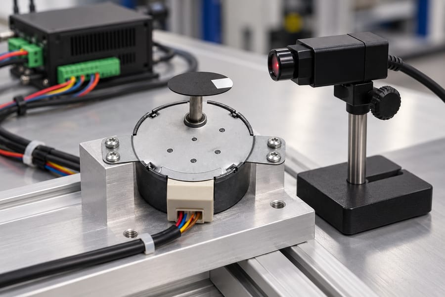
The target output speed is an application requirement, whereas achievable speed depends on the motor, drive, power supply, load, and transmission.
The motor and gearbox must deliver the required output speed and sufficient torque at the same operating point.
A controller may command the calculated motor speed without the motor successfully reaching it. Insufficient torque, excessive acceleration demand, or operating conditions outside the usable torque-speed range can cause stalling or missed steps.
Account for startup, acceleration, deceleration, and any speed changes during the cycle. If the machine requires 60 rpm only during steady operation, the acceleration profile must still allow the system to reach that speed reliably.
Also establish whether the required speed is continuous or intermittent. A motor capable of reaching a particular speed briefly may not sustain the same operating point throughout a demanding production cycle.
Calculate Usable Output Torque at the Required Speed
A gearbox can increase output torque by trading rotational speed for mechanical advantage. However, the useful torque depends on the motor’s actual running torque at the required speed and the gearbox’s transmission efficiency.
For a first-order estimate, use:
Output torque = motor running torque × reduction ratio × gearbox efficiency
Efficiency is expressed as a decimal in this equation. For example, 80% efficiency is entered as 0.80 rather than 80.
The motor running torque must come from an applicable torque-speed curve or validated operating data. The relevant curve should match the selected drive, current settings, supply voltage, and other specified operating conditions.
Holding torque is not a substitute for running torque.
Holding torque describes the motor’s ability to resist rotation when stationary under specified conditions; it does not establish the torque available while the motor rotates at 180, 300, or 480 rpm.
This distinction matters because available stepper torque generally changes with speed. A higher reduction ratio may increase theoretical torque multiplication while forcing the motor into a speed range where its running torque is substantially lower.
The following example illustrates how those competing effects influence ratio selection.
Every motor torque and efficiency value in the table is an explicit assumption for calculation purposes, not a measured torque curve, product specification, or performance claim.
| Reduction ratio | Required motor speed at 60 rpm output | Assumed motor running torque | Assumed gearbox efficiency | Calculated output torque |
| 3:1 | 180 rpm | 0.45 Nm | 85% | 1.1475 Nm |
| 5:1 | 300 rpm | 0.32 Nm | 80% | 1.28 Nm |
| 8:1 | 480 rpm | 0.18 Nm | 72% | 1.0368 Nm |
For the 3:1 candidate, the calculation is 0.45 × 3 × 0.85 = 1.1475 Nm. The 5:1 candidate produces 0.32 × 5 × 0.80 = 1.28 Nm under its separate assumptions.
For the 8:1 candidate, the result is 0.18 × 8 × 0.72 = 1.0368 Nm. Although this candidate has the greatest reduction, its assumed motor torque and efficiency produce less output torque than either alternative.
The example demonstrates why comparing ratios alone is insufficient. A higher ratio may provide greater torque multiplication but deliver less usable output torque if the required motor speed reduces available running torque enough.
The assumed efficiencies also differ deliberately. Actual gearbox efficiency depends on the gearbox design, load, speed, lubrication, and operating conditions; it should not be treated as a universal constant.
When evaluating an actual geared stepper motor, verify that the motor and gearbox combination can meet the required output speed and torque together.
The calculated torque must also cover the application’s demand with an appropriate engineering margin.
Finally, compare usable output torque with the load’s actual requirements, including friction, gravity where applicable, acceleration, and transmission losses beyond the gearbox.
A candidate that meets steady-state torque alone may still fail during startup or rapid changes in speed.
Account for Inertia, Acceleration, and Gearbox Limits
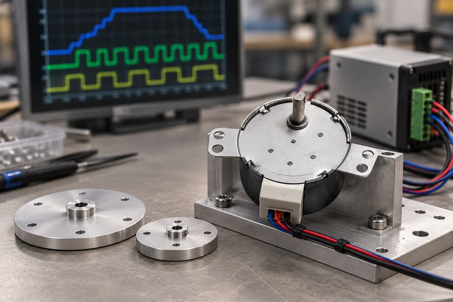
A gear ratio affects more than steady-state speed and torque. It changes the inertia seen by the motor, the acceleration required from the rotor, and the mechanical and electronic limits governing the complete drive system.
Reflect the Output Load Inertia to the Motor Shaft
For an ideal gearbox with reduction ratio i, the output-side load inertia reflected to the motor shaft is calculated as follows:
Reflected load inertia = J_load / i²
Here, J_load represents the total rotational inertia on the gearbox output side, and i is the motor-speed-to-output-speed ratio. This relationship assumes an ideal transmission with a fixed ratio.
For example, a 3:1 reduction reflects one-ninth of the output load inertia to the motor shaft. A 5:1 reduction reflects one-twenty-fifth, while an 8:1 reduction reflects one-sixty-fourth.
Consequently, increasing the reduction ratio can make the driven load appear easier to accelerate from the motor’s perspective. However, this benefit alone does not establish which ratio delivers the best overall performance.
The inertia calculation must include relevant downstream rotating components, couplings, screws, and other mechanisms. Linear masses can also contribute equivalent rotational inertia when their motion is related to shaft rotation through a known transmission geometry.
For an initial comparison, calculate the reflected inertia for each candidate using the same load configuration. Avoid comparing one candidate’s complete mechanism against another candidate’s motor-and-gearbox assembly alone.
Account for Output Acceleration and Motor Rotor Inertia
Although a higher ratio reduces reflected load inertia, it also requires the motor to accelerate faster when the output follows the same acceleration profile. This relationship affects the torque needed during startup and speed changes.
For a fixed reduction ratio, the motor’s angular acceleration is:
Motor angular acceleration = i × output angular acceleration
Suppose a mechanism requires a particular output acceleration. Increasing the ratio from 3:1 to 8:1 makes the motor’s required angular acceleration increase by the ratio of 8/3, assuming the same output acceleration and transmission behavior.
The motor rotor also has inertia, which must be accelerated independently of the external load. Its acceleration torque is calculated using rotor inertia multiplied by motor angular acceleration.
Rotor acceleration torque = J_rotor × motor angular acceleration
Therefore, for the same output acceleration, the motor’s rotor-inertia torque increases in proportion to the reduction ratio. This effect can offset part of the torque benefit obtained by reducing reflected load inertia.
Under an ideal model, the output load’s inertial torque requirement, referred to the motor shaft, decreases with increasing ratio. However, the rotor’s own acceleration demand increases, so the complete torque balance matters.
The motor must provide enough running torque for load acceleration, rotor acceleration, friction, and process forces at the actual instantaneous speed.
A candidate that meets the final-speed torque requirement may still lack sufficient torque during acceleration.
When selecting a stepper motor, consider its available torque across the acceleration profile rather than checking only the starting position or final operating speed.
Account for Gearbox Inertia and Transmission Losses
Gearbox inertia must be included consistently in the mechanical model. Before applying any reflection formula, establish whether the specified inertia is referenced to the input shaft or output shaft.
If gearbox inertia is specified on the input side, add that inertia directly to the motor-side inertia budget.
If it is specified on the output side, reflect it to the motor shaft using the square of the reduction ratio.
For output-referred gearbox inertia, the ideal motor-side equivalent is J_gearbox,out / i². Do not divide an already input-referred inertia by the ratio squared again, because that would underestimate the acceleration demand.
Check the component definition before adding catalog values together. Some specifications may already include particular rotating elements, so confirm the measurement reference and included components before calculating the complete system inertia.
Transmission losses require similar care. If gearbox efficiency has already been applied when calculating the motor torque required for a specified output load, do not apply the same loss allowance a second time.
The ideal inertia-reflection equations do not account for gearbox friction, lubricant behavior, or other real transmission losses. Treat those effects separately using applicable gearbox data or a justified engineering model.
Check Gearbox Input and Output Ratings
The gearbox must satisfy both its input-side and output-side operating limits. A ratio that meets the calculated torque requirement remains unsuitable if its required motor speed exceeds the gearbox’s permitted input speed.
- Input speed: Check the motor’s required operating rpm against the gearbox’s rated input speed and any applicable duty restrictions.
- Input torque: Confirm that the gearbox can accept the motor’s continuous and transient torque demands, including acceleration and deceleration.
- Output torque: Compare the calculated load requirement with the gearbox’s continuous rating and permitted intermittent peak rating.
- Output speed: Confirm that the required speed is compatible with the gearbox’s operating limits under the intended load.
- Thermal duty: Account for operating speed, transmitted torque, cycle duration, starts, stops, and available heat dissipation.
- Backlash: Consider reversal-related lost motion and positioning requirements, particularly when the application repeatedly changes direction.
Continuous torque ratings apply to sustained operation, whereas peak ratings cover permitted short-duration loading under specified conditions.
A short acceleration peak should not be evaluated against a continuous rating alone, nor should an intermittent peak rating be treated as continuously available.
Gearbox thermal capacity also matters when a machine runs repeated cycles. A combination that handles a brief movement may experience excessive heating when the same movement occurs frequently with limited cooling time.
Backlash can affect repeatability and positioning after direction changes. Increasing the reduction ratio does not automatically eliminate gearbox lost motion, so assess the transmission’s mechanical characteristics alongside the motor’s commanded resolution.
Verify Pulse-Frequency and Control Bandwidth
A stepper motor’s required speed must also be achievable within the controller’s pulse-generation capability and the drive’s accepted input frequency. Higher reduction ratios can increase pulse demand even when output speed remains unchanged.
For a hypothetical 1.8-degree stepper motor with 200 full steps per revolution and a setting of 16 microsteps per full step, each motor revolution requires 3,200 command pulses.
At 180 rpm, the pulse rate is 9,600 pulses per second. At 480 rpm, it rises to 25,600 pulses per second, even though both examples could produce the same 60 rpm output with different ratios.
If a hypothetical controller is limited to 20,000 pulses per second, it cannot supply the required 25,600-pulse-per-second command stream. The design would need a compatible pulse source, revised microstepping, or a different operating configuration.
Changing microstepping affects command resolution and pulse demand, but does not guarantee improved absolute positioning accuracy or eliminate the motor’s torque limitations. Any revised setting must remain compatible with the drive and required motion profile.
Validate the Ratio Under Real Operating Conditions
Calculations narrow the candidate ratios, but the selected configuration must also satisfy the machine’s actual motion profile, load variation, thermal duty, and control requirements. Validation should use representative hardware and measurable acceptance criteria.
Establish Representative Load and Motion Conditions
Begin with the real driven mechanism, including its transmission components, payload, friction, and any external forces. Testing an unloaded motor alone cannot establish whether the assembled machine will perform reliably.
Reproduce the required output speed and acceleration profile, including startup, deceleration, direction changes, and positioning pauses. Include the heaviest expected load and other operating conditions that materially affect torque demand.
The test should cover the complete motion cycle rather than only steady rotation. Rapid acceleration may expose insufficient torque, while repeated starts and stops can increase thermal loading beyond that observed during a short demonstration.
Where the machine handles variable products or loads, select representative operating cases and document their differences. If the worst-case load cannot be tested directly, define a justified simulation method and explain its limitations.
Check Torque Margin Across the Operating Profile
Compare the calculated torque demand with the motor’s available running torque at each relevant motor speed. Include acceleration torque, friction, process forces, and transmission losses without counting the same contribution twice.
The pull-out torque curve identifies the boundary beyond which the motor may lose synchronism under specified operating conditions.
A pull-out torque-speed curve indicates the motor’s loss-of-synchronism boundary under stated conditions, not a guaranteed usable range for the complete machine.
Operating close to that boundary leaves little allowance for load variation, temperature changes, supply fluctuations, or mechanical differences. Establish a suitable torque margin using the application’s risk, uncertainty, and required reliability.
Do not apply one universal margin to every stepper application. The acceptable margin depends on the consequences of missed steps, the accuracy of the torque data, and the variability of the actual load.
Compare the Candidate Ratios Against Actual Requirements
The earlier hypothetical comparison favored the 5:1 candidate for calculated output torque under its assumed conditions. That result is provisional because the assumed running torques and efficiencies are not measured data.
The 3:1 candidate requires less motor speed for the same output speed, potentially simplifying pulse generation and preserving more available running torque. However, its greater reflected load inertia may increase motor-side acceleration demand.
The 8:1 candidate reduces the ideal load inertia reflected to the motor shaft, but requires higher motor speed and potentially greater rotor acceleration torque. Its pulse-frequency demand and gearbox input-speed limits also require closer scrutiny.
Recalculate each candidate using the selected motor’s applicable torque-speed data, actual gearbox specifications, and measured or defensibly estimated load characteristics. Retain only configurations that satisfy every critical requirement with an appropriate margin.
Verify Thermal Duty and Control Behavior
Run the machine through its intended continuous and intermittent operating cycles. Include dwell periods, repeated acceleration, and realistic pauses because these influence motor heating, gearbox losses, and available cooling time.
Measure motor and gearbox temperatures at documented locations using a consistent method. Continue testing until temperatures stabilize or the specified duty period is completed, and compare readings with the applicable component limits.
Check that the controller supports the necessary pulse rate at every commanded speed, including the highest operating point. Check pulse scaling, microstepping settings, acceleration commands, and the relationship between commanded movement and actual output displacement.
If power interruption or restart is relevant, test the expected recovery sequence under controlled conditions.
Establish whether the mechanism must retain position, return to a reference, release a load safely, or require re-homing before production resumes.
Document the Acceptance Criteria
Define the pass conditions before testing begins. Criteria should reflect the machine’s required throughput, positioning performance, load capacity, operating environment, and applicable component ratings rather than arbitrary universal tolerances.
| Verification item | Measurement or test | Machine-specific acceptance criterion |
| Output speed and torque | Measure speed and confirm performance under representative load | Required speed achieved without stalling or unacceptable speed deviation |
| Acceleration and positioning | Record motion profile, settling behavior, and position error | Application-defined acceleration, settling, and positioning requirements met |
| Torque margin | Compare demand with applicable torque-speed data | Agreed margin maintained across critical operating points |
| Thermal duty | Record motor and gearbox temperatures during representative cycles | Temperatures remain within documented limits |
| Pulse generation | Check command frequency, scaling, and achieved movement | Controller and drive remain within specified limits; commanded motion is reproduced |
| Power interruption, if relevant | Interrupt power and execute the specified recovery sequence | Required recovery, reference, and load-control behavior demonstrated |
Repeat critical tests to identify inconsistent results, missed steps, unexpected heating, or positioning drift. Record the load, speed, acceleration settings, supply conditions, measurement method, and component temperatures for each test.
Record the Selected Configuration and Acceptance Evidence
The final selection record should identify the motor and gearbox models, reduction ratio, applicable torque-speed data, driver settings, supply conditions, pulse scaling, and required output performance.
Include gearbox input and output ratings, reflected-inertia calculations, acceleration assumptions, thermal-duty conditions, and the agreed torque margin. Record any limits on continuous operation, peak loading, or restart behavior.
Retain test results, measured values, deviations, corrective actions, and approval against each acceptance criterion.
The approved configuration should be traceable to the tested hardware and settings, with documented evidence that the complete machine meets its required operating conditions.
A geared stepper layout affects more than the gearbox footprint: shaft direction, wiring, mounting access, and maintenance paths all compete for limited machine space.
Compare the complete installed envelope separately from the space needed to install, inspect, remove, or service the assembly; a compact outline can still create an awkward machine layout.
How Do Coaxial, Offset, and Right-Angle Geared Stepper Configurations Differ?
Coaxial inline means the motor shaft axis and gearbox output shaft axis lie on the same centerline. The gearbox may extend the assembly axially, so length along that axis often becomes the first packaging constraint.
Parallel-axis offset means the input and output shafts run parallel but occupy different centerlines. The offset can move the output toward a neighboring component, reducing one dimension while increasing another; check housing and shaft positions.
Right-angle describes input and output axes arranged at 90 degrees. It redirects motion around a corner, but the term describes shaft geometry rather than a specific gear mechanism or guaranteed package size.
A right-angle gearbox is not necessarily a worm gearbox. Bevel, worm, and other arrangements may provide perpendicular axes, depending on the design; likewise, do not assume a worm gearbox will hold a load without power.
Choose the geometry from the required shaft direction first, then compare real drawings. A layout label alone cannot establish overall dimensions, efficiency, allowable loads, backlash, or whether a particular configuration is offered.
| Layout | Shaft relationship | Main packaging question |
| Coaxial inline | Input and output share one axis | Is there enough axial room for the motor, gearbox, coupling, and shaft access? |
| Parallel-axis offset | Input and output axes are parallel but displaced | Does the offset clear adjacent parts without widening the assembly envelope? |
| Right-angle | Input and output axes are perpendicular | Is the turned output direction useful after allowing for housing, wiring, and service access? |
For dimensions and configuration details, review the geared stepper motor information, then verify the proposed assembly’s drawing and specifications instead of inferring availability or performance from its layout name.
How Do Installed and Service Envelopes Differ?
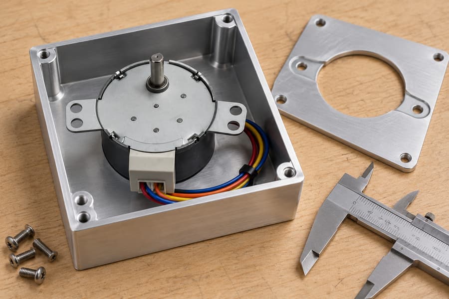
The installed envelope is the space occupied by the assembled unit in its normal operating position. Include the motor body, gearbox housing, projecting output shaft, coupling, mounting plate, fasteners, and any permanently attached accessories.
Do not measure only the gearbox outline. A coupling may extend the axial length, a mounting flange may add width, and a shaft or fastener may project beyond the housing’s nominal dimensions.
Electrical connections also consume real space. Allow for the connector body, plug removal direction, cable exit, minimum permitted cable-bend radius, strain relief, and the route needed to keep wiring clear of moving or hot components.
Installation orientation changes the envelope. A connector that clears a side panel in one position may face a frame after rotation; a shaft accessible from above may be blocked below a shelf.
The service envelope is the additional access space and movement path needed to inspect, adjust, disconnect, remove, or replace components. It can include tool swing, fastener access, unplugging, and withdrawal.
Keep service space separate from permanent occupied volume in layout drawings. A removable cover may need temporary clearance while it is lifted away, but that removal space is not necessarily occupied during normal operation.
Service access remains important even when temporary. If a cover must slide sideways before lifting, or the gearbox must withdraw along its shaft axis, nearby guards and frames must leave that path clear.
Plan access around the task. Routine inspection may need visibility and a hand or tool opening; replacing a coupling, releasing a keyed shaft, or removing the assembly may need a longer path.
A useful drawing therefore shows at least two boundaries: the permanent installed envelope and the service envelope. Add cable-bend and connector-removal requirements explicitly, because neither is reliably represented by the bare motor or gearbox dimensions.
Before fixing the bay size, confirm installation direction, mounting face, shaft projection, coupling dimensions, connector orientation, cable specification, and removal sequence. Mark undecided clearances as design allowances, not verified dimensions.
Parallel offset is not right-angle geometry: both shaft axes remain parallel, while right-angle layouts turn the output axis by 90 degrees. This changes the connection to the driven mechanism.
Compare dimensions from the same reference points and in the intended mounting orientation. Overall length, width, and height alone can conceal shaft-center locations, connector protrusions, or a coupling that crosses the nominal housing boundary.
Also consider the sequence for removing adjacent parts. A gearbox may fit yet be impossible to withdraw until a belt, guard, or bracket is removed; document dependencies before releasing the layout.
Which Layout Fits a Hypothetical Machine Bay?
Assume a machine bay provides 220 × 180 × 160 mm of clear space, measured length × width × height. These are illustrative design assumptions, not Leili product dimensions or specifications.
For this example, each installed envelope includes the motor, gearbox, output shaft, coupling, mounting hardware, and connector body. Cable-bend allowance and service access are listed separately because they depend on routing and maintenance procedures.
A coaxial inline assembly may fit the bay’s 220 mm length on paper, yet a connector exiting along that axis can require additional bend space. The fixed assembly length is not the whole installed requirement.
A right-angle unit may shorten the length while placing its connector or housing across the available width.
A parallel-axis offset arrangement may use the middle ground, but its displaced shaft centerline still needs clearance around the driven mechanism.
| Hypothetical layout | Fixed installed envelope (L × W × H) | Cable-bend allowance | Resulting envelope check against 220 × 180 × 160 mm bay | Separate service-path requirement |
| Coaxial inline | 205 × 95 × 110 mm | +35 mm along length | 240 mm length exceeds the bay | 60 mm axial withdrawal path after uncoupling |
| Parallel-axis offset | 175 × 125 × 120 mm | +35 mm along width | 175 × 160 × 120 mm fits nominally | 45 mm side access for fasteners; 80 mm withdrawal path |
| Right-angle | 145 × 150 × 115 mm | +45 mm along width | 195 mm width exceeds the bay | 70 mm gearbox withdrawal path; connector unplug access |
Every figure in this table is hypothetical. The resulting envelope check adds the stated cable allowance only along its assumed direction; it does not convert maintenance clearance into permanent occupied volume.
The comparison shows why one-axis length is insufficient. The inline layout passes the length check before cable routing but fails after its bend allowance; the right-angle layout fails the width check.
The offset example passes the assumed installed-envelope check, but it is not automatically the best choice. Its output shaft position, coupling alignment, and separate withdrawal path must also work within the real machine.
Service-path dimensions are independent of the permanent envelope. A removal path may extend through an access panel or into a temporarily cleared aisle, provided the maintenance procedure genuinely permits that space to be available.
Output Bearing Loads and Lever-Arm Effects
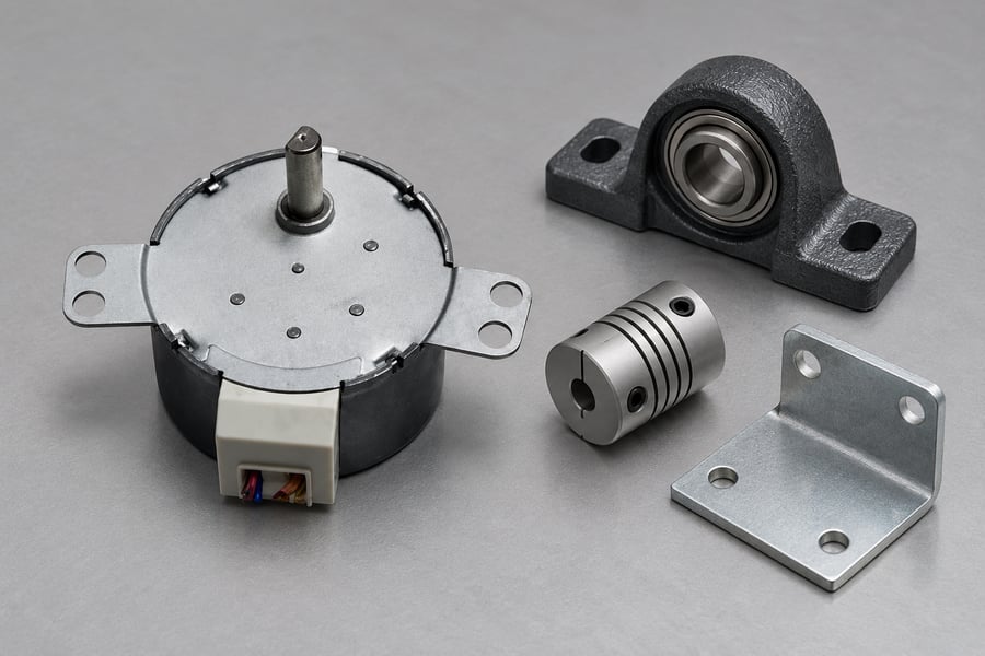
Packaging changes can alter how the driven load acts on the gearbox output. A pulley, belt, sprocket, or coupling may apply radial or axial force, depending on the transmission arrangement.
An overhung load acts at a distance from the supporting bearing. Its bending effect increases with both force and offset distance, so moving a driven component outward can raise bearing demand without changing its mass.
Measure the perpendicular distance from the selected bearing reference to the applied force’s line of action, then multiply that distance by the force to determine the bending moment.
Real designs may also require belt pretension, acceleration forces, shock loads, and load direction to be considered.
Do not assume the gearbox output shaft can carry the driven mechanism directly. Check the specified radial and axial load limits, the distance at which each limit applies, and any restrictions on simultaneous loading.
A right-angle arrangement may redirect the drive but place the load farther from a bearing. An inline arrangement can also create excessive overhang when a long coupling or pulley is added.
Compare candidate layouts using the actual shaft extension, coupling geometry, driven-component center of load, and bearing support. If the external load exceeds the gearbox’s permitted capacity, a separate support bearing may be necessary.
Design-Specific Efficiency and Gearbox Ratings
Gearbox efficiency depends on the particular transmission design and operating conditions, not simply whether the shafts are inline, offset, or perpendicular. Gear geometry, stage count, ratio, speed, load, and temperature can all affect losses.
Avoid treating all right-angle gearboxes as less efficient or all worm arrangements as self-locking.
Self-locking behavior, where relevant, depends on the specific design and operating conditions; it should not be used as an assumed safety or holding function.
Check rated output torque alongside input speed, duty cycle, permissible peak loads, and thermal limits. A nominal torque figure alone may not describe continuous operation, repeated acceleration, or an application with frequent starts and stops.
Check that the gearbox’s allowable torque is compatible with the stepper motor’s torque capability at the required operating speed.
Holding torque does not represent usable dynamic torque throughout the operating range; check the motor data at the required operating point.
Use Leili’s stepper motor information as a starting point for motor-side requirements, then compare the actual candidate’s documented ratings rather than assuming every layout has the same performance.
Mounting Orientation and Lubrication
Mounting orientation can affect lubrication distribution, heat dissipation, and access to mounting hardware. Confirm the gearbox manufacturer’s permitted orientations rather than assuming every position is acceptable.
A gearbox mounted vertically may place the motor, output shaft, or lubricant reservoir differently from a horizontal installation. Verify orientation-specific restrictions, lubricant requirements, and any associated rating changes before fixing the machine frame.
Lubrication requirements depend on the gearbox design and its specified operating conditions. Check the approved lubricant type, filling procedure, maintenance interval, and any restrictions affecting continuous operation or temperature.
The physical mounting arrangement also influences serviceability. A bracket that improves stiffness may obstruct a fill plug, inspection point, or fastener, making routine maintenance difficult without disturbing adjacent equipment.
Reversal Duty, Backlash, Reflected Inertia, Speed and Available Torque
Frequent reversals impose different demands from steady unidirectional rotation. Each acceleration, deceleration, and direction change affects motor torque demand, gearbox loading, positioning behavior, and potentially the mechanism’s service life.
Backlash describes lost motion when the output changes direction before the opposite tooth flanks or transmission elements engage. Its effect becomes particularly noticeable when an axis repeatedly approaches a target from alternating directions.
The relationship between gearbox backlash and final positioning error depends on the transmission ratio and measurement reference. Assess output-side motion directly where practical instead of converting nominal gearbox figures into an assumed machine accuracy.
A gearbox with lower backlash is not automatically the best choice for every application. Consider the required positioning tolerance, reversal frequency, loading direction, compliance elsewhere in the drive train, and repeatability under actual operating conditions.
Reflected inertia also affects layout selection. For an ideal reduction ratio i, the load inertia reflected to the motor shaft is Jload/i2, excluding gearbox inertia and transmission losses.
This relationship helps estimate motor-side acceleration demand, but it does not replace the manufacturer’s ratings. Gearbox input inertia, output-side inertia, friction, compliance, and dynamic load behavior still influence the complete system.
Higher reduction ratios can reduce reflected load inertia while increasing motor speed for a given output speed. Check whether the motor can supply sufficient torque at that operating speed, including acceleration and reversal peaks.
Available stepper motor torque varies with operating speed and drive conditions. Compare the required torque profile against documented motor performance, allowing for the selected gearbox’s losses rather than relying on standstill holding torque.
Consider the entire motion cycle, including dwell periods and repeated starts. A gearbox that handles an occasional peak may still experience unacceptable heating when the same event occurs continuously throughout production.
Mechanical resonance, coupling compliance, and frame flexibility can also affect positioning during reversals. Evaluate the assembled axis rather than attributing every oscillation or settling problem to the gearbox alone.
How Should the Selected Layout Be Verified?
Begin with supplier drawings for the exact proposed motor and gearbox configuration. Confirm housing dimensions, shaft centerlines, output projection, mounting interfaces, permitted orientation, and documented mechanical and thermal ratings.
Overlay those dimensions onto the machine assembly in its intended installation direction. Include the coupling, driven components, fasteners, connector bodies, guards, and surrounding structure rather than checking the motor and gearbox independently.
Cable clearance must be maintained during normal operation, not merely during maintenance. Verify the actual cable exit direction, specified bend radius, connector engagement, strain relief, and routing throughout the mechanism’s complete movement.
Check the cable path at travel limits and during acceleration, where movement or vibration may bring wiring closer to adjacent parts. A route that fits in the stationary drawing can still interfere during operation.
Evaluate maintenance access separately from operational clearances. Determine whether technicians can reach fasteners with the specified tools, disconnect electrical connections, release the coupling, and withdraw the assembly along its required removal path.
If removal requires temporarily taking off a guard or adjacent bracket, document that sequence. Confirm that the procedure is practical and that the required temporary clearance can actually be provided at the installation site.
Once the geometry is approved, test the assembled axis with its representative load. Exercise the intended speeds, acceleration profiles, reversal frequency, dwell periods, and operating cycle rather than relying solely on unloaded rotation.
Measure motor and gearbox temperatures over a representative duty period, comparing results with the applicable documented limits. Investigate unexpected heating, noise, vibration, or changes in motion before accepting the configuration.
Verify positioning and repeatability using the machine’s actual measurement reference. Test approaches from both directions, representative load conditions, and relevant operating temperatures, recording observed errors against application-specific acceptance criteria.
Where positioning degrades after repeated reversals, investigate backlash, coupling movement, structural compliance, and thermal effects separately. Record the test method, instrument resolution, operating conditions, and any adjustments made before repeating acceptance measurements.
The final approval record should identify the selected motor and gearbox, the approved drawing and revision, and the installation orientation.
Attach measured clearance results, cable-routing verification, service-access evidence, and motion, temperature, and positioning test results to establish the accepted configuration.