
Lead-screw pitch, screw lead, and permanent magnet (PM) stepper motor torque jointly determine the linear thrust available from a rotary drive. Their relationship also affects travel speed, mechanical efficiency, and load capacity.
Selecting a suitable combination requires more than comparing motor torque ratings. Engineers must evaluate operating speed, acceleration, friction, screw geometry, and mechanical constraints under actual application conditions.
Understanding Lead-Screw Pitch, Lead, and Linear Travel
What Is Lead-Screw Pitch?
Lead-screw pitch is the axial distance between corresponding points on two adjacent threads. It describes thread spacing and helps define the geometry of the screw and its mating nut.
For a single-start screw, one continuous helical thread runs along the shaft. A multistart screw has two or more independent helical threads, allowing greater axial travel during each revolution.
Pitch remains the distance between adjacent threads, regardless of how many starts the screw has. This distinction becomes important when calculating linear movement and mechanical advantage.
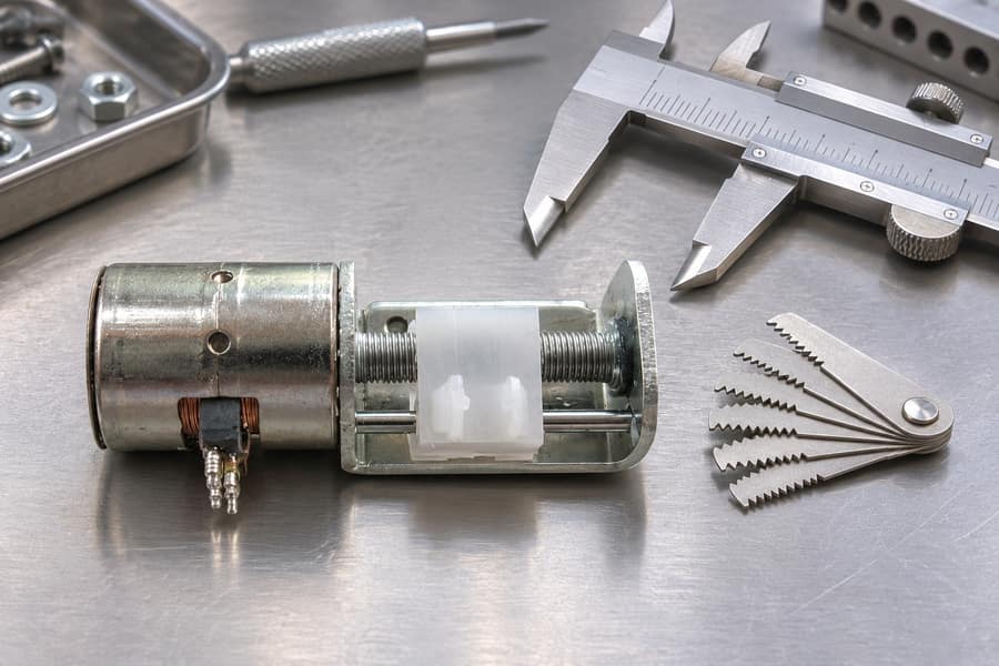
Pitch vs. Lead: Understanding the Difference
Lead represents the axial distance traveled by the nut during one complete screw revolution. Unlike pitch, it accounts for the number of independent thread starts.
The relationship is:
Lead = Pitch × Number of Starts
For a single-start screw, lead equals pitch. For a two-start screw, lead is twice the pitch, while a four-start screw produces four times the pitch as its lead.
A screw featuring a 0.5 mm thread pitch and two starts advances the nut by 1 mm with each complete revolution.
Confusing pitch with lead can produce incorrect calculations of both linear velocity and theoretical thrust. Engineers should therefore establish the actual lead before evaluating motor performance.
How Lead Determines Linear Travel and Speed
In a rotating-screw arrangement, each revolution advances a nonrotating nut by one lead. In a rotating-nut actuator, the screw translates instead; its anti-rotation arrangement must suit that architecture.
The required rotational speed can be calculated using:
n = 60v / L
Where:
- n = screw rotational speed in rpm
- v = required linear velocity per second
- L = screw lead per revolution
Velocity and lead must use matching distance units. The factor 60 converts revolutions per second into revolutions per minute.
Increasing the screw lead increases axial displacement per turn, allowing the required linear speed to be achieved at a lower rotational speed. However, it also reduces theoretical mechanical advantage when motor torque and efficiency remain unchanged.
A smaller lead provides greater theoretical thrust at a given torque but requires higher rotational speed to achieve the same linear velocity.
This creates an important design trade-off. Engineers must select lead according to both the required thrust and the available motor speed rather than optimizing either parameter independently.
How PM Stepper Motor Torque Determines Theoretical Linear Thrust
Holding Torque vs. Dynamic Torque
Holding torque describes the maximum static torque a stepper motor can resist when energized but stationary under specified conditions. It helps evaluate the motor’s ability to maintain position against an external disturbance.
However, holding torque does not represent the torque available during continuous rotation. A PM stepper motor’s available torque generally changes with rotational speed and operating conditions.
Dynamic torque is therefore more relevant when calculating thrust during movement. Engineers should obtain the motor’s torque-speed characteristics and identify the available torque at the required operating RPM.
The difference matters because a motor may have sufficient holding torque but insufficient running torque at the speed required by the application. Selecting a motor using only its holding torque can consequently overestimate its linear driving capability.
The Relationship Between Motor Torque and Screw Thrust
Motor torque produces rotational movement, which the lead screw converts into axial force. Mechanical efficiency accounts for energy lost during this conversion.
The steady driving-direction thrust estimate is:
F = 2π × η × T / L
Where:
- F = theoretical linear thrust in N
- η = screw mechanical efficiency
- T = available torque at the screw input in N·m
- L = screw lead in m/revolution
The equation assumes consistent SI units and steady movement in the driving direction. It expresses the relationship between rotational work and linear work while accounting for screw transmission losses.
Increasing available torque increases theoretical thrust proportionally. Increasing screw lead reduces theoretical thrust when torque and efficiency remain unchanged.
Efficiency also affects the result. A screw with greater mechanical efficiency converts more input torque into useful axial force, although actual efficiency depends on its geometry, lubrication, loading, and operating direction.
Understanding the Limits of the Thrust Equation
The calculated value represents theoretical steady screw thrust, not automatically the usable thrust at the machine’s moving load.
The equation accounts for the assumed screw efficiency but does not automatically include separate guide resistance, external bearing losses, or other mechanical losses outside the defined screw transmission.
Engineers must avoid counting the same loss twice. If an efficiency value already includes a particular component’s losses, those losses should not be deducted again.
For accurate selection, motor torque, screw efficiency, and additional mechanical resistance must be defined consistently.
Leili Motor provides permanent magnet stepper motor customization options, including winding, shaft, and lead-screw configurations. These options are relevant when matching motor characteristics and mechanical interfaces to a specific linear motion requirement.
How Speed, Acceleration, and Friction Affect Usable Thrust
Matching Motor Speed with Required Linear Velocity
Screw lead and target linear velocity establish the rotational speed required from the motor. This relationship should be evaluated before selecting a motor based on its torque rating.
Consider a system requiring 5 mm/s linear velocity with a screw lead of 1 mm per revolution.
Using n = 60v/L:
n = 60 × 5 / 1 = 300 rpm
The motor must therefore provide the required operating torque at approximately 300 rpm under the intended electrical and mechanical conditions.
A larger lead would reduce the required rotational speed, but theoretical thrust would also decrease at the same torque and efficiency.
A smaller lead would increase mechanical advantage while demanding higher motor speed. The selected combination must remain within the motor’s usable torque-speed operating range.
Acceleration and Rotational Inertia
Steady movement and acceleration create different torque requirements. During constant-speed operation, the motor supplies torque to overcome the load and mechanical resistance.
During acceleration, additional torque is needed to increase the rotational speed of the motor rotor, screw, coupling, and other rotating components.
The required acceleration torque can be expressed as:
T acceleration = J × α
Where:
- J = equivalent rotational inertia in kg·m²
- α = angular acceleration in rad/s²
The load’s inertia must also be considered. A translating mass contributes reflected rotational inertia through the screw mechanism, making acceleration requirements dependent on both load mass and screw lead.
Engineers should compare the total acceleration demand with the motor’s available dynamic torque at the relevant speed.
A motor that can maintain a load at constant speed may still lose synchronization during startup or rapid acceleration if the combined torque requirement exceeds its available output.
Deceleration and reversal also require attention because the direction and magnitude of acceleration torque change throughout the motion profile.
Breakaway Friction and Changes in Travel Direction
Before a stationary assembly can move, the driving force must first overcome the resistance created by static friction. The initial breakaway requirement can therefore exceed the torque needed for continuous movement.
Once movement begins, running friction becomes the primary resistance associated with the screw and supporting mechanism. Its magnitude depends on lubrication, thread geometry, nut preload, surface condition, and applied load.
Guide systems introduce additional resistance. Linear rails, sliding surfaces, seals, and other moving interfaces can consume part of the available thrust.
Reversal may also produce different resistance because load direction, preload, and mechanical clearances influence the required driving force.
Engineers should distinguish three conditions during evaluation: initial breakaway, steady movement, and direction changes. Treating them as one constant friction value can lead to inadequate motor selection.
Mechanical Factors That Limit Linear Thrust
Screw Efficiency and Backdriving Behavior
Lead-screw efficiency describes how effectively rotational input is converted into linear output. Thread geometry, friction, materials, lubrication, and applied load all influence this value.
Driving efficiency and backdriving behavior are related but not interchangeable. A screw’s ability to resist reverse movement depends on its geometry and friction characteristics under actual operating conditions.
A smaller lead may increase mechanical advantage, but it does not establish universal self-locking behavior. Lubrication changes, vibration, wear, and external loading can influence whether a mechanism moves under an applied axial force.
If a design must maintain position without continuous motor energization, engineers should evaluate backdriving behavior and determine whether an additional holding mechanism is necessary.
Efficiency should also be selected for the intended direction of travel. A value established under one condition should not automatically be applied to every operating direction or load.
Thrust Bearings and Axial Load Support
Thrust bearings support axial forces generated within a screw-driven mechanism. Their arrangement determines how loads are transferred into the machine frame.
Motor torque transmission and axial load support are separate engineering functions. A motor may generate sufficient rotational torque without having a shaft or bearing arrangement suitable for supporting the application’s external axial load.
The bearing configuration should therefore be checked for axial capacity, mounting stiffness, alignment, and allowable clearance.
Engineers should also identify where the screw’s axial reaction forces are transferred. Depending on the design, a dedicated thrust-bearing arrangement may be required to prevent excessive loading of the motor shaft.
Bearing friction can introduce additional losses. If these losses are outside the screw efficiency definition, they should be assessed separately rather than included twice.
Screw Buckling and Critical Speed
Long, slender screws operating under compression may buckle when axial loading exceeds their structural capacity. Unsupported length, screw diameter, material properties, and end-support conditions influence the buckling limit.
Critical speed represents a different constraint. It relates to the rotational speed at which screw vibration and dynamic instability can become problematic.
A screw may therefore reach its buckling or critical-speed limitation before the motor reaches its theoretical thrust capability.
Both conditions must be evaluated using the actual screw dimensions and support arrangement. A motor with greater torque does not eliminate these mechanical restrictions.
Anti-Rotation and Linear Guidance
The screw nut must be prevented from rotating when the intended output is linear translation. This usually requires a suitable guide system or another mechanical anti-rotation feature.
Guide rails also maintain the moving assembly’s alignment. Inadequate guidance can introduce side loading, increase friction, and cause uneven movement.
The guide system must support the relevant loads without imposing excessive resistance on the screw mechanism.
Consequently, screw strength, bearing support, anti-rotation, and guide capacity should be evaluated as separate parts of the complete mechanical design.
How to Calculate and Verify Usable Linear Thrust
A Practical Linear Thrust Calculation Method
A reliable calculation begins with the application’s motion requirements rather than an isolated motor torque figure.
First, define the required linear thrust, travel speed, stroke, and operating direction. Establish the screw pitch and number of starts to determine the actual lead.
Next, calculate the required rotational speed using the target linear velocity. Consult the motor’s torque-speed characteristics to identify available dynamic torque at that operating RPM.
Then select a realistic screw efficiency based on the expected mechanical configuration and lubrication conditions. Use this value to estimate steady driving-direction thrust.
Finally, assess acceleration torque, breakaway resistance, guide friction, bearing losses, and structural limits independently.
This sequence separates the theoretical torque-to-thrust conversion from additional application requirements. It also prevents engineers from treating a calculated steady thrust value as an approved continuous working load.
Hypothetical PM Stepper Motor Thrust Calculation
Consider a hypothetical screw-driven mechanism with the following operating parameters:
- Available dynamic motor torque: 0.020 N·m
- Screw lead: 1 mm/revolution
- Screw efficiency: 0.30
- Required linear velocity: 5 mm/s
The motor torque is assumed to be verified at 300 rpm under the stated operating conditions.
First, convert the screw lead into meters:
L = 1 mm = 0.001 m/revolution
Calculate the required motor speed:
n = 60 × 5 / 1 = 300 rpm
Next, estimate the theoretical steady thrust:
F = 2π × 0.30 × 0.020 / 0.001
F ≈ 37.7 N
Illustrative calculation only. This result is not a Leili Motor product rating or guaranteed working thrust.
The estimated 37.7 N represents steady driving-direction screw thrust before separate guide and other external mechanical losses.
The assumed dynamic torque must genuinely be available at 300 rpm. If acceleration requires additional motor torque, that demand must be evaluated separately using the rotating and reflected load inertia.
For example, the torque remaining to drive the axial load during an acceleration phase is lower when part of the available motor torque is being used to accelerate rotating components.
Guide resistance and separate bearing losses must also be considered. They should not be deducted again if already included in the efficiency value used for the screw calculation.
Understanding the Main Parameters
The following table summarizes how screw geometry and motor characteristics influence linear performance.
| Parameter | Engineering meaning | Influence on linear performance |
| Thread pitch | Distance between adjacent threads | Defines thread spacing |
| Number of starts | Independent thread starts | Determines lead with pitch |
| Screw lead | Travel per revolution | Influences speed and mechanical advantage |
| Dynamic torque | Available torque at operating RPM | Determines driving capability |
| Screw efficiency | Rotational-to-linear transmission efficiency | Influences theoretical thrust |
| Motor speed | Rotational speed in rpm | Determines achievable linear velocity |
These parameters must be evaluated together. For example, increasing lead changes both the required RPM and the theoretical thrust available from a given motor torque.
Practical Performance Verification
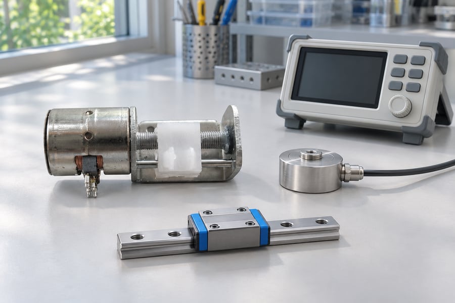
Calculation establishes an initial design estimate, but representative testing is necessary to verify the assembled mechanism.
Testing should cover startup under representative loading, continuous movement at the target speed, and acceleration or reversal where required.
Measure actual linear displacement and repeatability rather than relying exclusively on commanded motor steps. Monitor motor temperature, vibration, noise, and abnormal mechanical friction during operation.
The tested configuration should match the intended screw, nut, bearings, guides, lubrication, and mounting arrangement. Changes to these components can alter mechanical performance.
Selecting a PM Stepper Motor and Lead Screw for Your Application
Define Application Requirements Before Selection
Motor and screw selection should begin with clearly defined operating requirements. These include target thrust, linear velocity, stroke, acceleration, and duty cycle.
Engineers should identify whether the mechanism experiences compressive or tensile loading, as well as any external forces caused by gravity or connected equipment.
Required positioning precision and consistency between repeated movements are additional factors in component selection. The screw mechanism, motor control, mechanical clearances, and guide arrangement must collectively support the required positioning performance.
Installation space, shaft interfaces, and mounting dimensions should be established before finalizing the configuration.
Match Motor Torque, Screw Lead, and Mechanical Configuration
Once application requirements are established, compare available dynamic motor torque with the calculated operating demand.
Evaluate alternative screw leads against the required speed and thrust. Check whether the motor can achieve the required RPM without losing the torque needed to overcome the load.
Mechanical compatibility is equally important. Shaft dimensions, screw interfaces, mounting arrangements, and axial support must suit the intended assembly.
For compact applications, integrated PM stepper motor and lead-screw configurations may simplify the rotary-to-linear transmission arrangement.
For example, Leili Motor’s 065BY25T PM stepper motor with a miniature screw mechanism provides a product reference for compact screw-driven configurations. The product’s specific construction and available axial force should be verified using confirmed specifications, not assumed from its description.
Integrated linear actuation is another option when controlled axial movement is required. Leili Motor’s 25BY412 PM stepper motor linear actuator provides a relevant example for valve-control applications.
Request a configuration-specific drawing and test conditions so that axial force, travel, winding data and duty limits have an agreed meaning before selection.
Supplier Handover: Information Required for Motor and Screw Selection
A useful supplier handover should communicate the application requirements and mechanical configuration clearly. Providing only a target thrust value does not establish whether a proposed motor and screw combination is suitable.
| Selection category | Information to confirm |
| Linear requirements | Target thrust, speed, stroke, and travel direction |
| Screw configuration | Pitch, starts, lead, diameter, and length |
| Motor performance | Required RPM and available dynamic torque |
| Motion profile | Acceleration, deceleration, reversal, and duty cycle |
| Mechanical arrangement | Bearings, guides, mounting, and anti-rotation |
| Operating conditions | Lubrication, temperature, and loading environment |
| Structural requirements | Buckling, critical speed, and axial load support |
| Customization | Winding, shaft, and lead-screw configuration |
These details allow the supplier to assess motor and screw compatibility against the intended application.
The final selection should be based on the complete motor-and-screw configuration, with dynamic torque, mechanical losses, axial load support, and operating limits verified before production approval.