
Comparing hybrid stepper torque curves requires consistent winding temperatures and controlled electrical and mechanical test conditions. Otherwise, measured differences may reflect thermal variations rather than motor performance.
Engineers must distinguish average winding temperature from case temperature and local hot spots. Reliable comparisons require repeatable measurements, clearly defined test procedures, and documented operating conditions.
Why Winding Temperature Matters When Comparing Torque Curves
Two motors tested in the same room may have different internal temperatures. Differences in winding construction, thermal contact, mounting arrangements, operating history, and cooling conditions can produce different thermal states.
Actual Winding Temperature Versus Case and Ambient Temperature
Ambient temperature describes the surrounding environment, not the temperature inside the motor windings. Case temperature represents the motor housing surface and provides another useful but indirect thermal reference.
The winding temperature can differ substantially from both measurements during operation. Heat must travel from the conductors through insulation, internal components, and the motor housing before reaching the surrounding air.
This creates thermal gradients and delays. A motor case may still feel relatively cool while its windings are warming, particularly during continuous operation or repeated acceleration cycles.
How Temperature Influences Torque-Curve Interpretation
Copper resistance increases as winding temperature rises. In a voltage-limited operating condition, higher resistance can reduce available current, potentially affecting the motor’s torque performance.
However, the relationship depends on the drive system. Most modern stepper motor applications use current-regulated drivers rather than applying a fixed voltage directly to the windings.
When the driver maintains the commanded phase current, increased winding resistance alone does not necessarily reduce phase current at low speeds. This remains true while sufficient voltage headroom is available.
As motor speed rises, winding inductance and back electromotive force increasingly challenge the driver’s ability to regulate phase current. The higher winding resistance also increases the voltage demand on the driver when it attempts to sustain the specified phase current.
How to Estimate Average Winding Temperature Using Copper Resistance
Copper resistance provides a practical method for estimating average winding temperature without placing a sensor inside every winding location. The method compares measured resistance against a known reference value.
Reference Resistance and Copper Temperature Coefficient
For copper windings, the resistance-temperature relationship can be approximated over an appropriate temperature range using the following equation:
T_hot = T_ref + (R_hot/R_ref – 1)/alpha_ref
Where:
- T_hot:
Estimated average winding temperature at the measurement condition, in °C. - T_ref:
Reference winding temperature, in °C. - R_hot:
Winding resistance measured at the later temperature. - R_ref:
Winding resistance measured at the reference temperature. - alpha_ref:
Qualified copper resistance temperature coefficient, expressed per °C at the reference temperature.
The coefficient must correspond to the conductor material and reference-temperature basis. A commonly used approximate copper coefficient is 0.00393 per °C near 20°C, but the applicable value should be verified for the actual winding material.
Consider a hypothetical calculation using a reference resistance of 2.00 ohms at 20°C and a later measured resistance of 2.40 ohms.
Using 0.00393 per °C as the illustrative coefficient gives:
T_hot = 20 + (2.40/2.00 – 1)/0.00393
T_hot = 20 + 50.89 = approximately 71°C.
This example illustrates the calculation only. These values are hypothetical and are not Leili Motor product measurements or specifications.
The calculation assumes that resistance changes primarily because of conductor temperature. Connections, measurement leads, contact resistance, and material variations can introduce additional errors.
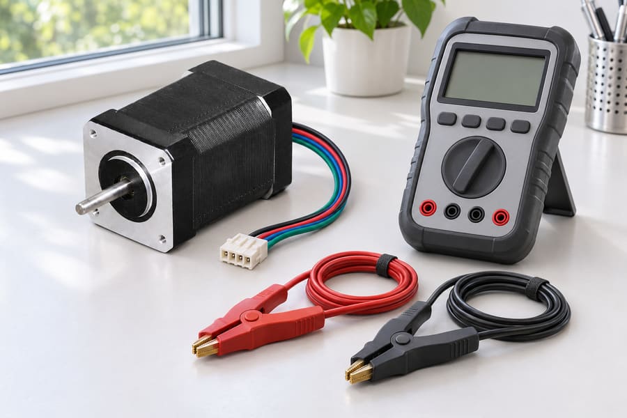
Safe Resistance Measurement and Thermal Limitations
Resistance measurements should be performed only after the motor is de-energized and safely isolated from its driver. The drive should be disconnected to prevent unintended electrical interaction during measurement.
The shutdown-to-measurement delay must be recorded because the winding begins cooling as soon as electrical heating stops. A long delay can produce an estimate lower than the temperature immediately before shutdown.
A consistent procedure is therefore essential:
- Isolation:
Remove electrical power and disconnect the driver before connecting resistance-measurement equipment. - Timing:
Record the shutdown time and the exact delay before each measurement. - Connections:
Use consistent terminals, lead arrangements, and contact procedures. - Measurement:
Apply an appropriate low-energy resistance measurement method. - Documentation:
Record measured resistance, reference values, and estimated temperature.
Local winding sections may operate at higher temperatures because heat generation and heat transfer are not perfectly uniform. End turns, tightly packed regions, and areas with limited heat dissipation may experience different thermal conditions.
Direct temperature measurements provide another source of information. Embedded sensors can monitor temperatures near their installation locations, although their readings do not necessarily represent the hottest winding point.
Engineers should distinguish three separate quantities: resistance-derived average winding temperature, directly measured temperature at a sensor location, and the maximum local hot-spot temperature.
These temperature readings represent different thermal conditions and must be evaluated separately. A winding-temperature estimate alone cannot establish that every insulation region remains below its applicable thermal limit.
Match Electrical, Mechanical, and Installation Conditions
Temperature control is only one part of a reliable comparison. Two torque curves may still differ because their electrical settings, mechanical loads, or installation arrangements are not equivalent.
Driver and Electrical Configuration
The DC bus voltage must be consistent between tests. A different supply voltage can change the available voltage headroom, particularly when the motor operates at higher speeds.
Phase current also requires careful documentation. Some specifications express current using an RMS convention, while others use peak current.
Comparing these values without confirming their definitions can create substantial errors. Engineers should establish whether the stated current represents phase current, winding current, or another driver-specific quantity.
Microstep settings should also match. Different microstep configurations can influence current waveforms, positioning behavior, and the interpretation of torque measurements.
Wiring arrangements require equal attention. Series and parallel winding connections, where applicable, can produce different electrical characteristics and must be identified in the test records.
Leili Motor provides different hybrid stepper motor configurations. Engineers should identify the exact configuration under evaluation rather than assuming that motors sharing a general product category have identical electrical characteristics.
Optional encoders and brakes should be documented when included. Their presence can change the assembled configuration, wiring requirements, or mechanical arrangement, even when the torque measurement focuses on the motor itself.
Mechanical Loading and Cooling Conditions
The mechanical test arrangement must reproduce equivalent operating conditions. Differences in mounting rigidity, alignment, coupling arrangements, and load inertia can affect measured acceleration and running behavior.
The acceleration profile must therefore be specified. Engineers should record acceleration rates, deceleration conditions, and any programmed speed changes used during the test.
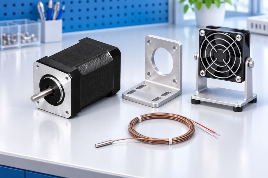
Cooling conditions should also remain consistent. Mounting a motor against a large metal fixture may provide a different heat-transfer path from installing it on an insulating support.
Airflow, surrounding temperatures, contact surfaces, and fixture dimensions should be documented. These factors influence thermal stabilization and may change the relationship between winding and case temperatures.
The following checklist identifies conditions that should remain controlled or explicitly recorded.
| Test category | Parameters to control or document | Reason for comparison |
| Electrical supply | DC bus voltage and stability | Influences available voltage headroom |
| Phase current | RMS or peak convention and commanded value | Prevents inconsistent current comparisons |
| Driver settings | Microstep resolution and current regulation | Maintains equivalent electrical operation |
| Wiring | Series or parallel arrangement and connections | Identifies winding configuration differences |
| Motor configuration | Frame, shaft, winding, encoder, and brake | Establishes the actual tested assembly |
| Mechanical loading | Load inertia, coupling, and alignment | Controls dynamic operating demand |
| Acceleration | Acceleration and deceleration profiles | Ensures comparable transient conditions |
| Installation | Mounting rigidity and contact surfaces | Identifies mechanical and thermal differences |
| Cooling | Airflow, ambient conditions, and fixture arrangement | Controls heat dissipation |
| Temperature | Winding resistance, temperature estimate, and timing | Establishes thermal comparability |
If a test parameter cannot be matched, its difference should be recorded and assessed before interpreting the results. Uncontrolled changes should not be attributed automatically to motor design.
Distinguish Pull-In Torque from Pull-Out Torque
Hybrid stepper motor torque specifications can describe different operating capabilities. Pull-in torque, pull-out torque, and holding torque represent separate conditions and should not be treated as interchangeable measurements.
Pull-In Torque: Starting Without an Acceleration Ramp
Pull-in torque is the highest load a stepper motor can handle when starting, stopping, or reversing directly at a specified stepping frequency without losing synchronism under the stated test conditions.
The motor starts directly at the specified pulse rate without requiring an acceleration ramp. Its ability to follow the commanded motion depends on available torque, load inertia, and operating conditions.
The test should identify the starting frequency, load inertia, acceleration assumptions, driver configuration, and synchronization acceptance criteria.
Pull-Out Torque: Maximum Running Load
Pull-out torque describes the maximum load torque a synchronized motor can sustain at a specified running speed before losing synchronism under the defined test conditions.
Unlike pull-in testing, the motor is first accelerated into its operating range. The load is then increased or otherwise adjusted until the motor can no longer maintain synchronization.
Pull-out torque is particularly relevant when evaluating motors used in continuously rotating applications. However, the measured value depends on the acceleration procedure, test duration, driver settings, and load arrangement.
Holding Torque: Static Position Maintenance
Holding torque describes the maximum external torque a stationary, energized motor can resist without losing its holding position.
It is measured under static conditions rather than during continuous rotation. The specified phase-current condition and winding connection must be documented.
Holding torque does not describe the torque available at a particular running speed. It should not be substituted for pull-in or pull-out performance when selecting a motor for dynamic applications.
Establish and Maintain the Same Winding Temperature
Once electrical and mechanical conditions have been defined, engineers should establish a repeatable thermal procedure. Merely starting two motors at the same ambient temperature does not ensure equivalent winding conditions.
The test should specify a target winding-temperature window, the stabilization method, and the measurement procedure used to confirm thermal consistency.
Heat-Soak Before Torque Measurement
A suitable procedure begins with the motor installed in its intended test arrangement. The driver, current settings, and cooling conditions should match the configuration specified for the comparison.
The motor is then operated under a defined thermal conditioning profile. This profile should identify the applied current, operating pattern, duration, and relevant environmental conditions.
Engineers should avoid using an arbitrary waiting period as the only indication of thermal stabilization. Motor construction and mounting arrangements influence how quickly heat builds up and dissipates, so thermal response times can vary between test specimens.
Instead, stabilization should be assessed using repeated measurements. Winding resistance or an appropriate temperature sensor can help establish whether the thermal condition has become sufficiently stable.
Define a Winding-Temperature Acceptance Window
A target temperature window establishes the acceptable range for collecting torque measurements. Its width should reflect the accuracy and repeatability of the measurement system.
There is no universal temperature window suitable for every motor or comparison. Engineers must consider the motor’s design, applicable thermal limits, and the accuracy of their measurement procedure.
The test record should identify whether the reported temperature represents a resistance-derived average or a direct sensor reading. It should also identify the sensor location when direct measurements are used.
Repeat Measurements Instead of Applying a Fixed Correction
If a motor operates outside the specified temperature window, the preferred approach is to restore the required thermal condition and repeat the measurement.
A single temperature multiplier should not be applied to an entire torque-speed curve. Torque depends on several interacting electrical and mechanical factors that vary with operating speed.
Furthermore, equal average winding temperatures do not guarantee equal magnet temperatures. Rotor magnets and stator windings have different thermal paths and time constants.
Compare Torque Curves and Evaluate Measurement Uncertainty
After establishing equivalent test conditions, engineers can compare the measured torque-speed curves. The comparison should consider the entire operating range rather than focusing exclusively on rated holding torque or one selected speed.
Align Speed Ranges and Compare Operating Regions
First match speed units, torque units, current convention and the curve definition. Pulses per second require the step angle and microstep setting before conversion to revolutions per minute.
Torque should be compared at corresponding speeds. If one curve contains measurements at different speed intervals, engineers should identify the common operating range before making numerical comparisons.
Engineers should examine the shape of each curve, including the rate of torque reduction as speed increases. A similar low-speed value does not establish equivalent high-speed performance.
Where measurements are available at matching speeds, direct point-to-point comparisons are preferable. Interpolation may be used when necessary, but the method and measurement spacing should be documented.
Evaluate Repeatability and Measurement Uncertainty
Instrument accuracy should be considered separately from repeatability. Measurement accuracy indicates the closeness of a reading to the actual value; repeatability indicates how consistently the same procedure produces similar results under equivalent conditions.
Temperature uncertainty also affects interpretation. Resistance measurements may include errors from lead resistance, contact quality, timing delays, and uncertainty in the reference coefficient.
Mechanical measurement uncertainty can arise from torque transducer calibration, coupling alignment, vibration, and changing friction within the test arrangement.
When two curves differ only slightly, engineers should determine whether the observed difference exceeds the combined measurement uncertainty.
A difference smaller than the measurement uncertainty does not provide strong evidence of a real performance advantage. Repeated measurements and better-controlled conditions may be necessary.
| Uncertainty source | Potential influence | Information to request |
| Resistance measurement | Incorrect average winding-temperature estimate | Reference resistance, measurement method, and instrument accuracy |
| Copper coefficient | Temperature calculation error | Coefficient value and material basis |
| Cooling delay | Difference between operating and measured temperature | Shutdown-to-measurement timing |
| Temperature sensor | Local reading may not represent the entire winding | Sensor type and installation location |
| Torque measurement | Error in reported torque values | Transducer range, calibration, and accuracy |
| Speed measurement | Incorrect torque-speed alignment | Speed measurement method and resolution |
| Driver current | Inconsistent electromagnetic excitation | RMS or peak convention and current settings |
| Mechanical loading | Changes in dynamic torque demand | Load inertia and acceleration procedure |
| Thermal repeatability | Variation between repeated curves | Heat-soak procedure and acceptance window |
Engineers should also request the original measurement data rather than relying exclusively on plotted images. Raw data makes it easier to verify curve alignment, identify unusual points, and conduct independent comparisons.
What Test Data Should Engineers Request from Suppliers
A useful supplier evaluation requires more than a torque-speed chart. Engineers should request sufficient supporting information to determine how the measurements were produced and whether the results represent the intended application.
Leili Motor’s broader stepper motor range can provide a starting point for identifying motor families and configurations for evaluation. However, product configuration information should be distinguished from measured performance evidence.
Prepare a Practical Data Handover
Before accepting a torque-curve comparison, engineers should organize the required information into a common test record. Each motor should have an identifiable configuration and corresponding measurement dataset.
The handover should contain the following items:
- Motor identification:
Model reference, frame size, winding configuration, shaft arrangement, and installed accessories. - Electrical conditions:
DC bus voltage, phase-current value and convention, microstep settings, and driver details. - Mechanical conditions:
Mounting arrangement, coupling, load inertia, acceleration profile, and torque measurement method. - Thermal records:
Reference resistance, reference temperature, measured resistance, estimated average winding temperature, and measurement timing. - Test definitions:
Pull-in, pull-out, or holding torque identification, including the applicable operating procedure. - Measurement evidence:
Raw torque-speed data, instrument information, calibration records, repeatability results, and uncertainty estimates. - Acceptance requirements:
Agreed winding-temperature window, permitted test-condition deviations, and criteria for repeating measurements.
When any required information is unavailable, the missing item should be identified explicitly rather than replaced with an assumed value. The comparison record should retain the original supplier data, calculated temperature estimates, and any subsequent test results.