
Check a hybrid stepper’s bare shaft before fitting the coupling, using a stable fixture and a radial indicator at a documented measuring station. Record the full indicator movement.
Compare repeatable readings with the agreed drawing requirement. This inspection separates measurement setup problems from shaft or bearing issues before the coupled assembly introduces additional sources of variation.
Understand Shaft Runout and Measurement References
What Radial TIR Means
Shaft runout describes the variation observed when a rotating shaft surface is measured against a fixed reference. For a hybrid stepper motor, radial runout is commonly checked before installing a coupling or other transmission component.
TIR represents the full range of indicator movement, calculated from the highest and lowest readings recorded during one shaft revolution at a defined axial position. It describes the full observed reading range, not the distance from the reading range’s midpoint.
For example, suppose a dial indicator records a maximum reading of +0.012 mm and a minimum reading of -0.008 mm. The resulting TIR is 0.020 mm, calculated by subtracting the minimum from the maximum.
This example illustrates the calculation only. It is not a recommended tolerance or an acceptance limit for hybrid stepper motor shafts. Acceptance limits should be specified in the engineering drawing or an inspection procedure approved by the relevant parties.
A single-station radial TIR measurement describes the circular sweep at one axial position. It does not automatically establish the geometric condition of the entire shaft surface.
Distinguish Runout from Other Geometric Characteristics
Several geometric characteristics can influence shaft inspection results, but they describe different conditions.
- Diameter variation:
Differences in measured shaft diameter at specified positions or orientations. - Roundness:
Deviation of a cross-sectional profile from a theoretically circular shape. - Radial runout:
Indicator variation during rotation at a specified axial station relative to a rotational reference. - Total runout:
A drawing-defined geometric characteristic that evaluates the entire indicated surface while the part rotates about its datum axis.
A shaft can have acceptable diameter measurements but still produce an unexpected runout reading. Similarly, a local surface irregularity may affect radial TIR without establishing the condition of the complete cylindrical surface.
Runout also depends on how the motor is supported and mounted. Bearing clearance, fixture alignment, and the selected rotational reference can all influence the observed result.
Identify the Measurement Reference
Two inspection approaches should be distinguished before testing begins.
An as-assembled, bearing-supported measurement evaluates the shaft as it rotates in its installed motor bearings. This approach is useful for practical screening because it reflects the motor’s assembled mechanical condition.
A formal GD&T inspection may instead require rotation around a specified datum axis established through an approved measurement fixture. Its setup must follow the drawing’s datum references and geometric control requirements.
These methods are not automatically interchangeable. A bearing-supported screening result should not be presented as formal datum-axis acceptance unless the inspection arrangement satisfies the drawing requirements.
Prepare the Motor and Establish the Measurement Setup
Make the Motor Safe for Inspection
Before measuring, disconnect the motor from its driver and power supply. Keep the motor electrically unpowered throughout the check, with no external command capable of initiating rotation.
Manual rotation should be performed gently and deliberately. Do not use electrical pulses to rotate the shaft during a static dial-indicator inspection.
Avoid using pliers or other gripping tools that could scratch, deform, or otherwise damage the shaft. The shaft should be rotated through an accessible coupling feature or another suitable arrangement that does not damage its precision surfaces.
Hybrid stepper motors produce detent torque because of their magnetic structure. This resistance can make manual rotation feel uneven, but it does not independently indicate shaft bending or excessive runout.
Inspect the Shaft Surface
Clean the exposed shaft and inspect its condition before installing the indicator. Remove loose contamination using an appropriate nonabrasive cleaning method.
Look for visible scratches, corrosion, dents, burrs, and other surface irregularities. These conditions can influence the indicator reading or prevent reliable contact with the intended measurement surface.
Particular attention is needed when the shaft includes flats, keyways, chamfers, or stepped sections. These features interrupt the cylindrical measurement surface and should not be included in an ordinary radial sweep.
Only measure a continuous cylindrical land at the specified axial station. If the required location falls on an interrupted surface, do not average readings across the flat or keyway to produce an artificial TIR value.
Instead, document the geometry and request an agreed alternative inspection method. Depending on the drawing and measurement objective, this may require another measurement location or a different approved metrology arrangement.
If a burr is discovered, record its location and condition. Never file, grind, or otherwise modify a precision shaft without explicit approval because material removal can change the geometry being inspected.
Position the Motor and Dial Indicator
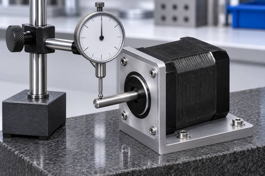
The motor must be supported by a stable fixture that provides the correct reference for the intended inspection. A suitable arrangement may use the mounting flange or locating pilot, depending on the drawing and measurement objective.
Poor fixture seating can introduce apparent shaft movement that does not originate from the shaft surface itself. Check the mounting interface for contamination, uneven contact, and looseness before proceeding.
Position the dial indicator so its plunger follows the local radial direction, perpendicular to the shaft axis. An angled contact arrangement can introduce cosine error and reduce measurement reliability.
Select an indicator with suitable resolution and measurement range for the specified inspection requirement. Excessive contact force should be avoided because it can influence readings, particularly when bearing support or fixture stiffness is limited.
The measuring tip should remain in stable contact throughout rotation. Confirm that the fixture, indicator stand, and motor mounting arrangement do not move when the shaft is turned.
Measure and Record Radial Shaft TIR
After establishing the reference and confirming the measurement surface, perform the inspection using a consistent procedure. The objective is to obtain repeatable readings without introducing unnecessary mechanical loading.
Follow a Consistent Measurement Sequence
Step 1: Confirm the measurement station.
Identify the specified axial location from the drawing or inspection instruction. Record its position relative to a clearly defined shaft feature or reference face.
Step 2: Check indicator contact.
Confirm that the indicator tip rests on a continuous cylindrical land. Make sure the plunger is aligned radially, perpendicular to the shaft axis and that the measuring tip does not touch a chamfer or adjacent shoulder.
Step 3: Rotate the shaft manually.
Gently rotate the unpowered shaft through one complete revolution. Maintain consistent movement without forcing the shaft or applying unnecessary axial pressure.
Step 4: Record the reading range.
Observe the maximum and minimum readings during the rotation. Record both signed values rather than documenting only the calculated difference.
Step 5: Determine the TIR value.
Take the lowest recorded reading away from the highest reading to obtain the total indicator variation. Retain the full difference as TIR; do not divide the result by two when reporting total indicator reading.
Step 6: Repeat the measurement.
Return to the measurement position and repeat the sweep. If the results differ, investigate fixture movement, indicator contact, mounting stability, and bearing-supported movement before deciding whether the shaft is unacceptable.
Use an Inspection Record
A measurement record should contain enough information for another inspector to understand how the result was obtained.
| Inspection item | Information to record | Purpose |
| Motor identification | Model or inspection reference | Identify the tested motor |
| Mounting reference | Flange, pilot, or specified datum arrangement | Establish the measurement basis |
| Axial station | Distance from the defined reference face | Identify the measurement location |
| Surface condition | Cleanliness, burrs, flats, keyways, or damage | Confirm measurement suitability |
| Maximum reading | Signed indicator value | Preserve the upper reading |
| Minimum reading | Signed indicator value | Preserve the lower reading |
| Calculated TIR | Maximum minus minimum | Report the full reading range |
| Repeat readings | Results from repeated sweeps | Assess measurement consistency |
| Inspection equipment | Indicator identification and resolution | Support traceability |
For example, a record showing +0.012 mm maximum and -0.008 mm minimum produces 0.020 mm TIR. Retain the maximum and minimum values in the inspection report to provide a traceable basis for verifying the calculated result.
Do not report only the final number when measurement conditions may affect interpretation. The mounting reference, axial station, surface condition, and repeated readings provide important context.
Diagnose Abnormal or Inconsistent Readings
An unexpected indicator reading does not automatically prove that the shaft is bent or defective. Several mechanical and measurement conditions can produce similar observations.
The diagnosis should begin with the inspection setup and proceed toward the motor’s mechanical components. This approach reduces the risk of rejecting a component because of an avoidable measurement error.
Check Fixture and Mounting Conditions
A loose motor mounting arrangement can cause the indicator reading to change as the shaft rotates. Even small movements at the fixture interface may influence the apparent radial sweep.
Check whether the flange or pilot is seated correctly. Inspect the mounting surfaces for contamination, uneven contact, or damage that could prevent repeatable positioning.
The indicator stand should also remain stable. If the readings change when the fixture is touched or the measurement is repeated, verify the complete setup before attributing the variation to the shaft.
Consider Bearing Clearance and Shaft Movement
Hybrid stepper motor shafts are supported by bearings, so bearing condition and clearance can influence the measured result. Radial movement under changing contact conditions may produce readings that differ between repeated measurements.
Observe whether the shaft remains consistently supported during the inspection. If the measurement changes with slight changes in applied contact force, bearing-supported movement or fixture compliance may require further investigation.
Do not automatically classify such behavior as shaft bending. A bearing-supported measurement reflects the assembled mechanical system, including its support conditions.
Inspect the Shaft Surface and Geometry
Localized scratches, dents, burrs, or surface irregularities can produce changes as the indicator passes over them. Their locations should be recorded rather than treated as representative of the entire shaft.
A shaft with a flat or keyway near the measurement position may also produce discontinuous contact. Such geometry makes an ordinary continuous radial sweep unsuitable at that location.
The appropriate response is to identify the affected feature and obtain an agreed measurement method. Averaging interrupted readings does not establish a valid cylindrical runout result.
Use Observations to Guide Further Checks
| Observed condition | Possible contributing factor | Recommended verification |
| Readings change between repeated sweeps | Fixture movement or unstable indicator contact | Check mounting and indicator stand stability |
| Localized reading peak | Burr, scratch, dent, or surface irregularity | Inspect and document the contact area |
| Variation changes with contact force | Bearing clearance or fixture compliance | Review bearing support and measurement loading |
| Reading changes after remounting | Different seating or reference conditions | Verify flange and pilot contact |
| Indicator loses contact near a flat | Interrupted measurement surface | Request an agreed alternative method |
| Consistent abnormal readings | Shaft geometry or assembled mechanical deviation | Compare with drawing requirements and investigate the reference condition |
Detent torque should not be used as a diagnostic substitute for indicator measurements. Magnetic resistance during manual rotation is a normal characteristic of stepper motor construction and does not quantify shaft runout.
Evaluate Measurements Against Drawing Requirements
Once the measurement is repeatable, compare the recorded result with the applicable drawing or approved inspection specification. Acceptance should be based on the correct geometric characteristic, measurement reference, and specified location.
Confirm the Correct Tolerance Requirement
A drawing may specify radial runout at a particular station, total runout over a cylindrical surface, or another geometric characteristic. These requirements cannot be treated as equivalent simply because they involve an indicator.
For example, a single-station circular sweep provides information about one cross-section. A total-runout inspection evaluates variation across the controlled surface while referencing the specified datum axis.
The inspector must therefore identify what the drawing actually controls. Applying a total-runout limit directly to a single-station screening measurement may produce an incorrect acceptance decision.
Likewise, a bearing-supported motor measurement should not automatically replace a formal datum-axis inspection. If the drawing specifies a particular datum arrangement, the inspection must reproduce that arrangement or follow an approved alternative.
Measurement Uncertainty and Repeatability Considerations
The uncertainty associated with a measurement method determines how reliably its result can be assessed against a specified tolerance limit. Indicator resolution alone does not describe the complete uncertainty of the inspection.
Several factors can affect measurement reliability, including support rigidity, consistency of motor positioning, indicator contact alignment, bearing play, surface quality, and inspection technique.
When a measurement approaches an acceptance boundary, verify the setup and repeat the inspection. Consider whether the uncertainty of the measurement method is sufficiently small for the decision being made.
A difference between repeated readings should be investigated before rejection. It may indicate inconsistent mounting, changing contact conditions, or movement within the bearing-supported assembly.
If the result remains questionable, use an agreed higher-confidence measurement method rather than assigning a cause without supporting evidence.
Keep Screening and Formal Acceptance Separate
A practical pre-coupling check can help identify obvious mechanical concerns before additional components are installed. However, screening is not necessarily equivalent to a complete dimensional acceptance inspection.
The inspection report should identify whether the result represents as-assembled bearing-supported radial TIR or a formal GD&T measurement around a specified datum axis.
This distinction is particularly important when different inspection departments or suppliers use different fixtures. Two readings cannot be compared reliably unless their reference arrangements and measurement objectives are understood.
Verify Shaft and Coupling Runout After Assembly
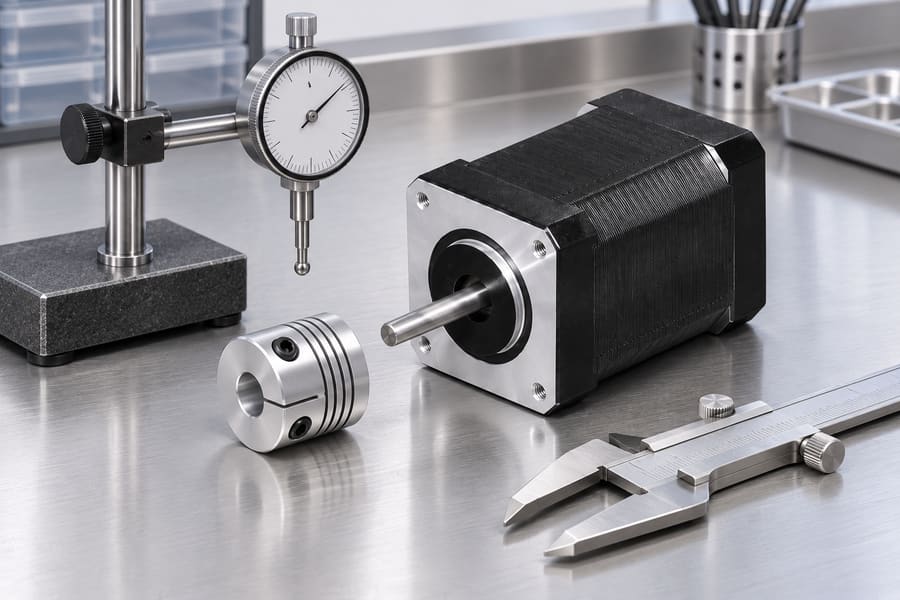
Passing the pre-coupling inspection does not eliminate the need to inspect the assembled interface. Installing a coupling or hub introduces additional contact surfaces and mounting conditions that can affect the final result.
Inspect Coupling and Hub Runout
After installing the coupling, check its seating and engagement with the motor shaft. Confirm that the hub is positioned correctly and that the installation process has not introduced visible damage or unintended movement.
Where required, measure the coupling or hub using an appropriate reference. Record the measurement location and indicate whether the reading represents the external cylindrical surface, bore-related geometry, or another specified feature.
An important distinction is that coupling outside-diameter runout does not necessarily establish bore eccentricity. The external surface and internal bore are separate geometric features and may have different relationships to the rotational axis.
If the drawing controls bore position relative to the coupling’s functional axis, the inspection must address that requirement directly. Measuring only the outside diameter may not provide sufficient evidence.
Evaluate the Complete Coupled Assembly
Check the assembled arrangement for shaft engagement, hub seating, and alignment against the applicable design requirements. Where the assembly specification requires additional measurements, perform them using the designated reference and inspection method.
A flexible coupling can accommodate certain forms of angular, parallel, or axial misalignment within its design limits. However, it should not be treated as a universal correction for excessive shaft runout, incorrect mounting, or defective coupling geometry.
Excessive mechanical deviation can still affect transmitted motion, loading, vibration, and bearing performance. The coupling’s flexibility does not remove the need to establish acceptable shaft and hub conditions.
If an assembled measurement differs from the original shaft reading, investigate the installation interface before assigning the cause. Possible contributors include hub seating, bore geometry, mounting position, and changes in the measurement reference.
Consider Shaft Customization Requirements
Shaft geometry and motor mounting dimensions should be considered together when selecting a hybrid stepper motor for a particular coupling arrangement. Specify the shaft diameter, overall length, locating details, and motor frame dimensions before manufacturing begins.
Leili Motor provides hybrid stepper motor shaft options and frame customization according to application requirements. These options allow the mechanical interface to be specified for the intended assembly.
Different stepper motor configurations may also have different mounting and shaft arrangements. Buyers should communicate the required inspection reference and drawing-defined geometric characteristics rather than assuming that customization establishes a universal runout guarantee.
Complete the Assembly and Inspection Release Record
Before releasing the motor for coupling installation or subsequent assembly, retain the inspection evidence and document any unresolved conditions.
The release record should include:
- Motor identification:
Model, production reference, and relevant drawing revision. - Inspection method:
Bearing-supported screening or formal datum-axis inspection. - Measurement location:
Defined axial station and applicable cylindrical land. - Surface condition:
Recorded burrs, damage, flats, keyways, or other measurement limitations. - Measurement results:
Maximum reading, minimum reading, calculated TIR, and repeated results. - Acceptance reference:
Applicable drawing characteristic and approved tolerance. - Assembly verification:
Coupling or hub inspection results where required. - Disposition:
Accepted, held for investigation, or referred for an approved alternative inspection method.
The record should preserve the original measurement data rather than only stating that the shaft passed inspection. This makes subsequent assembly decisions traceable and helps distinguish shaft-related variation from mounting or coupling-related changes.