
Axial flux motors (AFMs), also known as pancake motors, offer distinct advantages over their radial flux counterparts—including high power density, compact form, and efficient thermal management. Central to their performance are magnet configurations, particularly in single-rotor and double-rotor designs.
Understanding differences in magnetic layout, flux behavior, performance metrics, and trade-offs is essential to choosing the optimal configuration.
Axial Flux Motor Basics
Axial flux motors generate electromagnetic torque via interaction between permanent magnets (usually rare-earth) on a disc-shaped rotor and windings on a stator, typically sandwiching one or more rotor discs. Characteristics include:
- Compact axial length — resulting in higher torque density (Nm per liter)
- Short magnetic flux path — reduces magnetic losses and enables high efficiency
- Surface- or interior-mounted magnets — affects flux penetration and mechanical protection
Magnet configurations influence:
- Flux density in the air gap (B_g)
- Cogging torque
- Thermal performance
- Mechanical complexity
Key magnet layout types:
- Surface-Mounted Permanent Magnets (SPM)
- Interior Permanent Magnets (IPM)
- Halbach arrays (a specialized SPM array enhancing one-sided flux)
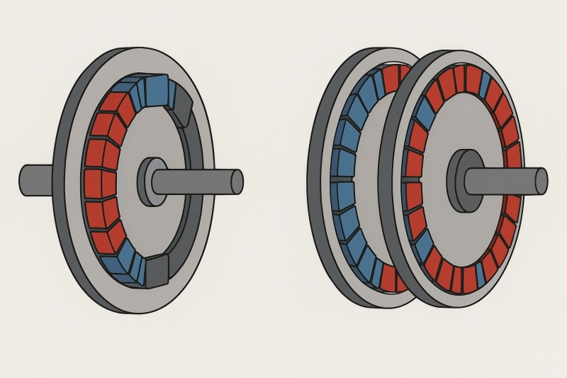
Single Rotor Configuration
In this design:
- One rotor disc bears magnets, typically facing a stator on one side.
- Commonly arranged as rotor–stator–[air gap]–housing.
Magnetic Behavior
- Flux crosses a single air gap.
- Magnetic circuit simpler: one stator–rotor interface.
- Ease of manufacturing and assembly.
Performance Characteristics
- Cogging Torque: Present; design mitigations like skewing or fractional slot winding help.
- Efficiency: High, but slightly lower than double-rotor due to single-sided flux utilization.
- Thermal Management: Easier—stator and windings accessible.
Use Cases
- E-bikes, drones, appliances, low-cost industrial motors.
- Applications where thickness must remain minimal.
| Advantages | Disadvantages |
| – Simple design – Easier cooling – Lower cost |
– Lower torque density – One-sided flux only |
Double Rotor Configuration
Two rotor discs, each with magnets, sandwich the stator in a rotor–stator–rotor (R–S–R) arrangement.
Essentially, two flux paths operate in parallel.
Magnetic Behavior
- Dual air gaps: one between each rotor and stator.
- Flux splits across two gaps; ideally symmetric to maximize utilization.
- Magnetic flux density can be higher for same magnet volume.
Performance Characteristics
- Torque Density (T_d): Generally higher than single rotor, due to doubled interacting surface.
- Torque Calculation: Approximate torque scales near 2× single rotor (minus minor leakage losses).
- Cogging Torque: Can be reduced if rotor magnet poles are offset relative to each other or stator.
- Efficiency: Improved electrical-to-mechanical conversion due to better flux utilization.
- Complexity: Higher—requires supporting two rotors; mechanical alignment critical.
- Thermal Management: Slightly more complex due to sandwiched stator; but heat can flow from both sides to cooling surfaces.
Use Cases
- Automotive traction motors (EVs/hybrid systems)
- Heavy-duty industrial drives
- Applications demanding high torque in limited axial space
| Advantages | Disadvantages |
| – Higher torque density – Better efficiency – Lower cogging |
– Higher cost – Complex alignment – Harder cooling |
Quantitative Comparison
Below is a hypothetical comparative table based on typical small to medium-sized axial flux motors (e.g., 10 kW class), illustrating key metrics:
| Parameter | Single Rotor (SR) | Double Rotor (DR) |
| Air Gap Count | 1 | 2 |
| Magnet Volume (V_magnets) | 1 unit | ~1.8–2 units* |
| Peak Torque (Nm) | 50 | 90 |
| Torque Density (Nm/L) | 45 | 80 |
| Cogging Torque (% of T_peak) | 5% | 3% |
| Efficiency (%) | 93 | 95 |
| Axial Length (mm) | 100 | 150 |
| Structural Complexity | Low | Medium-high |
| Thermal Access | Excellent | Moderate |
| Estimated Cost Index | 1.0 | 1.3 (due to parts & assembly) |
DR requires more magnet material, but improved magnetic utilization may allow using slightly less per rotor than SR per rotor.
Notes on Data:
- Magnet Volume: A double-rotor design uses more magnets, but each rotor can be slightly thinner if the flux paths share better, sometimes resulting in ~1.8× rather than a full 2× increase.
- Torque Density: DR yields ~1.8× to 2× the torque, reflecting two active faces.
- Cogging: Offset magnet arrangement mitigates torque ripple better in DR.
- Efficiency: Gains derive from reduced magnetic leakage and better utilization—typically 1–2 percentage points.
- Axial Length: DR is thicker, impacting form factor.
- Cost: Higher due to more rotor parts, dual bearings, more complex assembly.
Design Considerations and Trade-offs
Magnet Usage & Material Cost
Rare-earth magnets (e.g., NdFeB) dominate cost.
DR uses more magnets, increasing cost—but higher performance may justify it.
Designers often balance magnet grade (remanence, coercivity) and volume.
Mechanical Complexity
SR: single shaft and rotor assembly, simpler bearings and alignment.
DR: requires two rotors, careful axial concentric alignment, often double bearings or a thrust bearing.
Structural Support & Stiffness
DR’s additional rotor adds weight and potential flex.
Housing must be robust to sustain torque and axial forces.
Cooling & Thermal Path
SR: stator typically on exterior, easy to cool.
DR: stator is in the middle—an internal stator requires heat paths both sides, often using cooling plates or fluid channels.
Magnetic Design Complexity
Flux cancellation and leakage must be controlled.
Cogging reduction strategies: skewing, fractional slots, magnet angular offset (especially effective in DR by anti-phase rotor placement).
Control Strategy
Both use typical control (e.g., field-oriented control), but DR may have symmetric inductance profiles aiding smoother control.
Applications and Case Examples
Electric Vehicles and Traction
Double Rotor AFMs excel where axial space exists (e.g., between output shaft and chassis).
Example: A 50 kW DR AFM used in an EV delivers high torque density—peak 300 Nm in a 180 mm thick motor pack.
Aerospace and Drones
Single Rotor AFMs favored in lightweight, thin packages (e.g., propeller-driven drones).
Example: A 5 kW pancake motor, diameter 200 mm, axial length 60 mm, weighing 2 kg—suitable for multicopter propulsion.
Industrial Automation
Both types used for servo motors or direct-drive applications.
DR proves advantageous in limited axial envelope but high torque need (e.g., robotic joints).
Simulated Performance Modeling
Consider two simulated 20 kW motors for a robotics application:
SR Model:
- Diameter: 250 mm
- Axial length: 90 mm
- Magnet volume: 0.005 m³ equivalent
- Simulated flux density (B_g): 0.8 T
- Peak torque: ~200 Nm
- Estimated efficiency: 93%
DR Model:
- Same diameter
- Axial length: 140 mm
- Magnet volume: 0.0085 m³ equivalent
- Simulated B_g per side: 0.75 T
- Peak torque: ~350 Nm
- Estimated efficiency: 95%
Key insights:
- DR achieves about 1.75× torque increase for ~1.7× magnet volume increase.
- Efficiency gain of ~2 points likely due to improved flux utilization and lower leakage.
Advanced Variants
Halbach Array AFM
Uses a magnet array that amplifies flux on one side and cancels it on the back.
In DR design, you can employ opposing Halbach arrays on both rotors to further concentrate flux through stator, boosting torque density but adding manufacturing complexity.
Interior Permanent Magnet (IPM) AFM
Embeds magnets within the rotor material.
Advantages: better mechanical protection, potential for flux weakening.
Both SR and DR IPM designs benefit, but DR IPM is rarer due to complexity.
Choosing between single-rotor (SR) and double-rotor (DR) configurations in axial flux motors depends on performance goals, space constraints, cost budgets, and integration complexity:
SR is ideal when simplicity, lower cost, and minimal axial thickness are priorities.
DR stands out when maximizing torque density and efficiency within allowable thickness, especially in high-performance or space-rich applications like EVs, industrial drives, or robotics.
Designers must consider magnet cost, mechanical alignment, cooling strategies, and cogging mitigation. With advances like Halbach arrays and IPM variants, the possibilities for optimizing AFM performance are expanding. Both SR and DR remain central to next-generation high-density motor design.