
An axial flux motor flange inspection should use the supplier’s approved drawing, defined datums, suitable measurement methods, and agreed limits for the assembled interface. A nominally matching bolt pattern does not establish correct location, alignment, or support. The inspection record must identify the flange feature and reference arrangement closely enough that the machine builder can connect the reading to the approved mounting requirement.
Which Drawing Should Control the Inspection?
Use the controlled drawing for the exact motor configuration and its mating interface. Confirm the revision, mounting orientation, locating features, and any adapter included in the assembly. A general product illustration or a drawing for another variant should not become the inspection authority by convenience.
For a model from the Leili axial flux motor range, obtain the relevant interface information before the machine structure is finalized. Identify which dimensions and geometric requirements the supplier controls and which belong to the machine builder. This division makes it clear who must resolve a mismatch.
The inspection plan should list the characteristics that matter to assembly and operation. Avoid measuring a large number of easy dimensions while leaving the locating relationship undefined. A short, targeted plan linked to drawing requirements is more useful than a long list of unconnected readings.
Why Are Datums More Important Than an Isolated Reading?
Datums establish the reference from which a feature is located or evaluated. Without them, two inspectors can produce different readings while both believe they are checking the same requirement. The fixture and measurement method should preserve the reference relationship intended by the drawing.
A face reading, pilot diameter, and shaft relationship answer different questions. Do not describe them all simply as alignment. The inspection record should use the drawing’s terminology and identify the feature, reference, and method for each result.
| Inspection Item | Reference Needed | Reason to Check |
| Locating feature | Specified datum system | Establish assembled position |
| Mounting face | Relevant reference axis or face | Assess the required relationship |
| Bolt arrangement | Drawing coordinates | Confirm assembly compatibility |
| Shaft interface | Approved shaft requirements | Support coupling integration |
| Adapter assembly | Complete locating scheme | Control accumulated variation |
If an adapter changes the reference path between motor and machine, include it in the inspection review. An acceptable motor flange and an acceptable adapter considered separately do not automatically establish an acceptable assembled relationship. The machine designer should define the relevant assembly requirement.
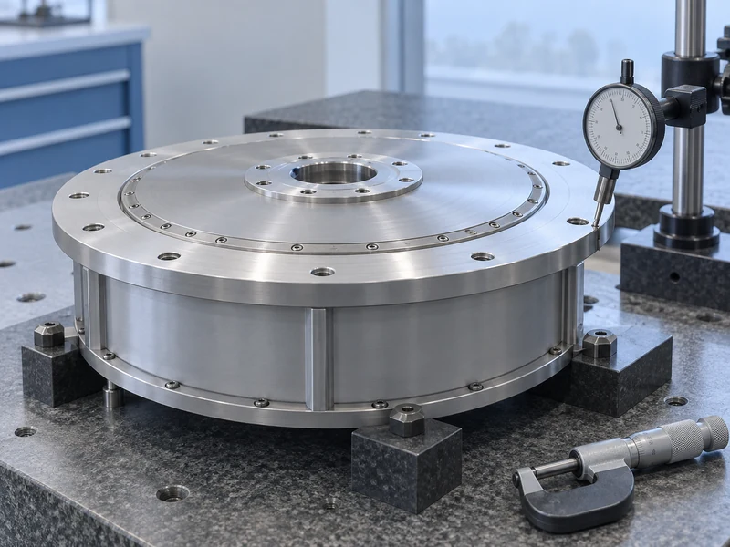
How Should the Measurement Method Be Selected?
Select a method capable of evaluating the specified feature and tolerance under practical conditions. Instrument resolution is only one consideration; setup, access, fixturing, and interpretation also influence the result. The inspector should be able to explain how the method relates to the drawing requirement.
NIST’s publication on coordinate measurement traceability and uncertainty distinguishes instrument calibration considerations from the uncertainty of a particular measurement task. Applied to flange acceptance, this means a calibration label alone is not a complete method justification. Document the task-specific setup and the limits of the resulting measurement.
Choose a method that can be repeated when a result is questioned. Record the relevant fixture, contact locations, and environmental conditions. A photograph can support the written record, but should not replace the definition of the measurand or the acceptance requirement.
Why Should Temperature Be Recorded?
Temperature can affect dimensions and the relationship between connected components. For precision interface work, record the relevant measurement conditions and follow the drawing or agreed procedure concerning reference temperature. Do not compare readings from materially different conditions without considering the effect.
NIST’s dimensional traceability guidance identifies thermal expansion as a factor in dimensional measurement uncertainty. The engineering implication is to distinguish cold inspection conditions from the machine’s operating condition. A drawing-based inspection may be necessary without being sufficient to establish behavior after the assembly heats during service.
Where operating thermal growth matters, the machine designer and motor supplier should agree how it is assessed. Do not invent a universal hot-alignment allowance for axial flux motors. The appropriate approach depends on materials, support geometry, temperature distribution, and the complete machine arrangement.
How Can Mounting Distortion Complicate the Result?
The assembled support arrangement can affect the motor interface, especially if mating surfaces or locating features are not prepared as intended. Follow the approved assembly instructions and investigate a result that changes unexpectedly after installation. The purpose is to understand the load path and locating condition rather than force the assembly to fit.
Leili’s discussion of axial flux motor integration with gearboxes and direct-drive systems provides related context for the complete mechanical arrangement. The flange review should include the selected coupling, adapter, and support structure. Each interface can influence the final relationship between the motor and driven equipment.
Avoid correcting an unexplained geometric result through an improvised machining or shimming change. Such changes may alter another required relationship or move responsibility between suppliers. Obtain an approved disposition that states what is being corrected and how the assembled result will be verified.
Does Motor Topology Provide a Universal Tolerance Limit?
An axial flux topology does not provide a universal external flange tolerance for every product. The approved design and intended integration determine the relevant limits. General descriptions of internal air-gap sensitivity should not be converted into an external installation tolerance without supplier confirmation.
Leili’s comparison of single-rotor and dual-rotor axial flux designs explains structural alternatives. Use that information as background when discussing the selected product. The inspection plan must still rely on model-specific drawings and instructions.
Similarly, a general article about the axial flux motor manufacturing process can explain why controlled production matters without establishing acceptance values for a particular installation. Keep process background separate from the requirements written into the purchase agreement. This avoids turning an explanatory statement into an unsupported contractual limit.
How Should a Borderline or Failed Reading Be Handled?
Preserve the original reading, setup details, and instrument information before making changes. Confirm that the correct drawing, datum, and method were used. A disagreement about the method should be resolved before deciding that the motor or mating part is out of tolerance.
For a reading near the tolerance boundary, use the decision rule established before inspection, including its treatment of measurement uncertainty, to determine the disposition. Do not repeatedly measure until a favorable value appears. The objective is a defensible assessment of the feature, with a documented disposition for any nonconformance.
If rework or a changed assembly arrangement is approved, record the change and repeat the affected checks. Retain both the original and final results so that the history remains understandable. The supplier and machine builder should agree whether other interface characteristics also need review.
How Should Two Different Inspection Results Be Reconciled?
If supplier and receiving inspection disagree, compare the measurement definitions before comparing the numbers. Confirm that both teams used the same feature, reference system, support condition, and drawing revision. A result taken on a loose component may answer a different question from one taken after the component is secured to an adapter.
Exchange enough setup information to reproduce the relevant measurement, including contact positions and the condition of the assembly. Then agree a method for resolving the discrepancy, with appropriate consideration of uncertainty. Repeated measurements made under different definitions will not settle the issue.
Keep the resolution attached to the inspection record so that the same disagreement is not repeated with the next delivery. If the drawing or procedure was unclear, revise the controlled document through the responsible engineering team. The aim is a shared interpretation of the required interface, not simply agreement on one favorable reading.
What Should the Final Mounting Acceptance Record Include?
Include the exact motor identification, drawing revisions, mating-part information, measurement methods, results, and approved exceptions. State whether the record concerns the loose motor, the adapter, or the complete assembled interface. These are different inspection scopes and should not share an ambiguous pass statement.
For a candidate on the Leili 30 kW axial flux motor page, identify the full variant before associating a drawing or report with it. Shared power does not imply identical mounting geometry. The acceptance package should make the link between physical unit and approved interface clear.
Keep the record available for future replacement and troubleshooting. It provides a baseline when the machine is dismantled, a different motor is proposed, or an operating symptom raises questions about the mounting arrangement. A well-defined flange inspection supports reliable integration because it verifies the relationship the machine actually depends on.