
An axial flux motor’s mechanical speed does not by itself establish the electrical frequency its inverter must supply. Electrical frequency depends on both rotational speed and the number of pole pairs, while the usable operating range also depends on the motor’s electrical characteristics and the converter’s capabilities. The enquiry should therefore identify the exact motor configuration and required speed range before a drive is selected.
How Are Mechanical Speed and Electrical Frequency Related?
For synchronous operation, electrical frequency equals mechanical speed in revolutions per minute multiplied by the number of pole pairs and divided by sixty. For this calculation, group the magnetic poles into north-south pairs; a sixteen-pole configuration therefore contributes eight pole pairs to the speed-frequency relationship. This relationship connects two different quantities and should not be confused with inverter switching frequency.
As a simple hypothetical example, a motor with eight pole pairs running at 1,500 rpm requires an electrical fundamental frequency of 200 Hz. A motor with six pole pairs at the same mechanical speed corresponds to 150 Hz. These arithmetic examples explain the relationship and are not instructions to operate an unidentified motor at either condition.
When selecting from Leili’s axial flux motor range, obtain the pole information or rated electrical frequency for the actual model. Do not infer it from the disc shape or from another motor in the family. Designs with similar mechanical appearance can have different electrical configurations.
Why Can Motors with the Same Power Need Different Frequency Ranges?
The same mechanical power can be delivered at different combinations of torque and speed. Designers can also use different pole counts and electrical arrangements. Consequently, a shared power rating does not establish a common inverter frequency requirement.
The published Leili 30 kW axial flux motor data include a TYP345XS variant at 1,500 rpm and 200 Hz and a TYP300XS variant at 3,000 rpm and 300 Hz. These listed pairs correspond to different pole-pair counts under the synchronous relationship. Confirm the exact supplied configuration rather than applying one variant’s frequency data to the entire group.
The required operating range may extend below or above the rated speed, but permission to do so must come from the supplier’s operating envelope. The arithmetic relationship identifies frequency; it does not establish allowable torque, voltage, mechanical speed, or thermal duty. Keep those separate checks in the selection record.
| Quantity | Meaning | Selection Use |
| Mechanical speed | Shaft revolutions per minute | Match the driven machine |
| Pole pairs | Magnetic configuration | Relate speed to frequency |
| Electrical frequency | Fundamental electrical cycle rate | Check drive support |
| Switching frequency | Converter switching behavior | Review converter conditions |
| Torque-speed envelope | Permitted mechanical duty | Validate the complete requirement |
Why Is Maximum Output Frequency Not a Complete Compatibility Check?
A converter’s maximum frequency is only one of several relevant limits. The drive must support the motor type, required current, voltage demand, control implementation, and protective functions across the intended operating range. A frequency number that appears sufficient on a specification sheet does not prove complete compatibility.
The supplier should review motor parameters using defined units and conventions. Back-EMF, resistance, and inductance information may be required depending on the drive’s approved setup method. Confirm which values are needed rather than populating fields with numbers taken from a different winding or another product family.
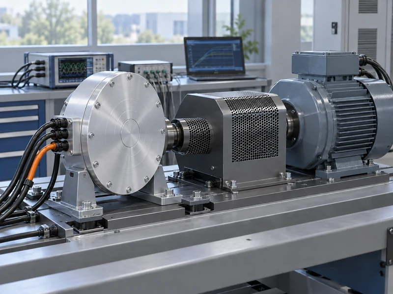
If the drive uses a motor identification procedure, agree its applicability and the permitted machine condition before commissioning. Some procedures have requirements concerning shaft motion or connected load. The machine integrator should resolve those requirements through the approved instructions instead of assuming every identification method is suitable for the installed equipment.
How Do Voltage and Current Limits Affect Higher-Speed Operation?
The required voltage and current depend on the motor and operating point, so speed capability cannot be assessed from frequency alone. A system can reach a voltage-related limit even when the converter permits a higher numerical frequency setting. The motor-drive envelope must therefore be checked under the actual supply conditions.
MIT’s permanent magnet machine course notes describe current and voltage constraints in PM machine operation. For procurement, request the confirmed envelope for the selected motor and inverter rather than extrapolating from a nominal frequency limit. Any field-weakening operation requires explicit model-specific confirmation.
Mechanical speed limits remain a separate requirement. A control configuration that can generate the necessary electrical frequency does not establish that the rotor, bearings, coupling, or driven equipment may operate at the resulting speed. The machine’s permitted range must satisfy all relevant limits together.
What Should Be Asked About Switching Frequency and Derating?
Ask the drive supplier which switching conditions are recommended for the motor and what consequences they have for usable current, losses, and thermal management. Do not assume that a higher switching setting is always preferable. The approved combination should reflect the motor, cable arrangement, converter, and application.
Keep electrical fundamental frequency and switching frequency in separate fields of the enquiry. If a switching-frequency entry is mistaken for the supported electrical fundamental frequency, the selection worksheet no longer answers the motor’s speed-range question. Request written clarification when a data sheet uses abbreviated terminology without defining the quantity.
Cooling should be reviewed under the actual electrical and mechanical operating states. Leili’s article on axial flux motor cooling methods gives background on the heat-removal arrangements. The supplier should confirm duty limits for the chosen control and cooling configuration rather than relying on a generic topology description.
Does the Rotor Arrangement Determine All Electrical Requirements?
No single topology label determines every parameter needed by the inverter. Pole count, winding configuration, magnetic design, and intended operating range are specific to the product. The electrical handover must identify the actual motor rather than a general category.
Leili’s comparison of single-rotor and dual-rotor axial flux motors helps explain structural alternatives. Use it to understand the design discussion, while obtaining the numerical parameters from the selected model’s controlled documentation. A familiar construction does not justify copying another motor’s drive setup.
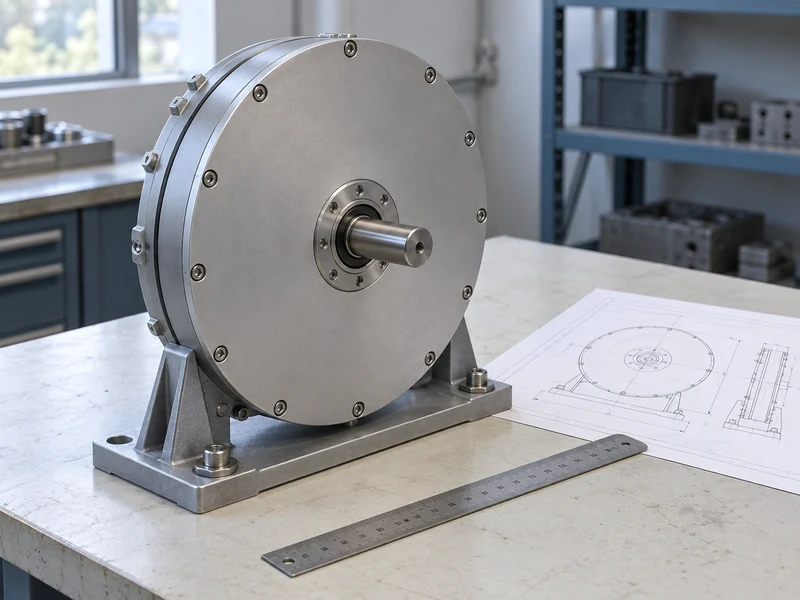
Manufacturing or configuration changes should be traceable when they affect electrical data. The related overview of the axial flux motor manufacturing process provides context for product consistency. The project record should state which configuration the supplied parameter set describes.
What Should the Motor-and-Drive Enquiry Contain?
Provide the required mechanical speed range, torque demand at important points, duty duration, and available supply conditions. Add the exact motor designation, pole information, rated frequency, electrical parameters, and feedback arrangement where applicable. State any parameter that remains unknown rather than substituting an assumption silently.
Request confirmation of the complete operating envelope and any configuration restrictions. The response should identify the proposed inverter, relevant software or options, and the basis for current and voltage suitability. Include the protection and cooling requirements that must remain in place during operation.
If alternative drive proposals are invited, require each supplier to use the same duty description. This makes differences in hardware, control requirements, and included services visible. It also prevents a nominal power comparison from concealing an unsupported part of the speed range.
What Can a Frequency Cross-Check Reveal in a Data Sheet?
A cross-check can identify an inconsistency that deserves clarification before parameters are entered. Calculate the implied pole-pair count from the listed speed and electrical frequency, then compare it with the supplier’s stated motor configuration. If the information does not agree, ask which value or definition applies rather than choosing the number that seems most familiar.
Possible explanations should be resolved through the supplier’s controlled documentation. A transcription mistake, a different variant, or an undefined quantity can each produce confusing data, but the buyer should not guess which explanation is correct. Keep the clarified information with the approved parameter set.
This review is especially useful when several motors share a power label or when a spreadsheet combines data from multiple suppliers. The calculation checks agreement among the listed speed, frequency, and pole information; it provides no measured evidence that the motor can deliver the required load. Passing it confirms only that the listed relationship makes sense; the current, voltage, thermal, mechanical, and control requirements still need their own review.
How Should the Match Be Verified During Commissioning?
Use the approved configuration and test plan to verify the required operating points under representative load. Record actual speed, relevant electrical observations, and the conditions that support the claimed duty. A successful unloaded run at a selected frequency is not proof of the loaded operating envelope.
Retain the final parameter backup and the motor data revision with the asset documentation. If the motor, inverter, software, or winding configuration changes, review the match before reusing the settings. Understanding the speed-frequency relationship is the first step; maintaining a verified motor-drive configuration is what makes that understanding useful in service.