
A permanent magnet synchronous motor acceleration requirement should state the load inertia, speed change, ramp time, resisting torque, and repetition pattern. Rated torque alone does not establish whether the motor and drive can accelerate the machine as required. The selection must satisfy the temporary torque demand while remaining within the approved electrical, mechanical, and thermal envelope over the complete cycle.
Why Is Acceleration a Separate Selection Question?
Steady operation requires torque to overcome the driven load and losses, while acceleration also requires torque to change rotational speed. A motor can satisfy the steady requirement yet fail to achieve the requested ramp with the available inverter current. Conversely, a system sized only for a short peak may carry unnecessary continuous capacity if its duty is not examined carefully.
Start with the candidate permanent magnet synchronous motor, then describe the machine’s motion cycle independently of the catalogue rating. This prevents the enquiry from becoming a request to confirm a motor selected before the load was understood. The supplier needs enough information to review both the required torque and the frequency of its occurrence.
Acceleration requirements should come from the process. If a faster ramp provides no useful production benefit, it may impose avoidable demands on the motor, inverter, coupling, and driven equipment. State the acceptable ramp range instead of automatically requesting the shortest achievable time.
How Is the Basic Acceleration Torque Calculated?
For a simplified rigid rotating system, acceleration torque is the total inertia referred to the motor shaft multiplied by angular acceleration. The required motor torque also includes the resisting load torque and relevant losses. This calculation is a starting model, with additional analysis needed where flexibility, changing load, or other dynamics are important.
Consider a hypothetical system with total referred inertia of 0.20 kg·m² accelerating from rest to 1,500 rpm in two seconds at constant acceleration. The speed change is approximately 157 rad/s, giving an acceleration torque of about 15.7 N·m before adding resisting torque and losses. These values illustrate the calculation and do not describe a Leili product or a tested machine.
If the resisting torque were 20 N·m throughout that illustrative ramp, the simplified combined requirement would be about 35.7 N·m before further allowances justified by the engineering model. If resistance changes with speed, calculate the demand across the ramp rather than adding a single convenient constant. Keep the assumptions visible alongside the result.
Which Inertias Need to Be Included?
Include the motor rotor, coupling, driven components, and any other rotating or translated mass whose motion is reflected at the motor shaft. Where gearing or another transmission is present, refer the load correctly through that arrangement. A load inertia stated at another shaft cannot simply be added without checking the speed relationship.
Request the exact motor’s rotor inertia where it materially affects the calculation. A different motor size or rotor design can change the acceleration requirement as well as the available torque. Leili’s explanation of surface-mounted and interior PMSM designs provides design background, but the calculation needs the selected model’s data.
| Input | Why It Matters | Preferred Evidence |
| Referred inertia | Sets acceleration demand | Drawings or validated calculation |
| Load torque | Adds to motion demand | Measured or modeled curve |
| Ramp profile | Defines acceleration over time | Process requirement |
| Cycle frequency | Determines repeated loading | Production schedule |
| Initial condition | Affects available thermal margin | Defined operating sequence |
A documented range is preferable to an unsupported exact value when inertia is uncertain. Ask the designer which components dominate the uncertainty and whether a practical measurement can reduce it. This focuses engineering effort on information that can change the selection.
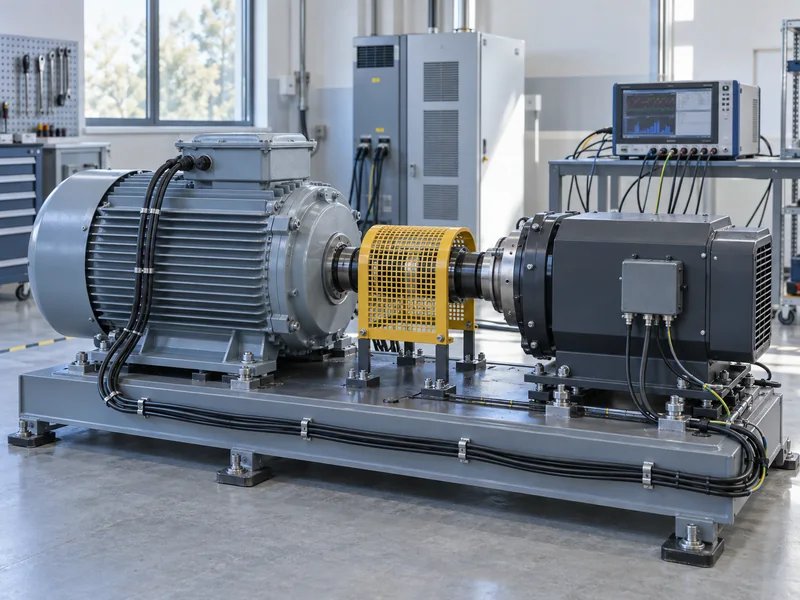
Why Must Peak Torque Be Checked Against Duration and Speed?
Peak torque is meaningful only with its permitted duration, operating speed, initial condition, and recovery requirements. A headline overload value does not establish that it is available throughout every ramp. The motor and inverter must both support the required demand under the same conditions.
At higher speed, the available operating envelope can also be constrained by voltage. MIT’s permanent magnet machine notes describe the interaction of current and voltage limits. For selection, obtain the applicable torque-speed envelope for the actual motor-drive combination rather than extrapolating a low-speed peak value.
Plot the required torque against speed and time, then compare it with the confirmed available envelope. If a ramp crosses an unsupported region, discuss a revised ramp, a different drive arrangement, or another motor selection. Increasing a setting does not establish that the hardware can safely provide the extra demand.
When Is RMS Torque Useful, and What Does It Miss?
RMS torque can be a useful screening quantity for a repeated cycle when the relationship between torque, current, and relevant losses supports that approximation. It gives greater weight to high-torque portions than a simple average. However, it does not automatically represent every loss mechanism or every thermal condition in a PMSM.
Calculate it from the complete cycle with each torque level and duration explicitly stated. Then ask the motor supplier whether the approximation is appropriate for the speed range, control mode, and cooling arrangement. A single RMS figure should not erase the sequence needed to assess peak temperature or repeated overload recovery.
Core losses, speed-dependent conditions, and changing ventilation can make two cycles with similar RMS torque behave differently. Leili’s article on PMSM overheating provides context for the thermal review. Final approval should use the supplier’s model-specific assessment of the actual cycle.
How Does the Ramp Shape Influence the Machine?
The same total speed change and duration can be achieved with different acceleration profiles. Those profiles can impose different peak torque and mechanical transition demands. Define the intended profile when it matters to the process rather than providing only the start speed, end speed, and elapsed time.
The control arrangement must be able to execute the approved motion while maintaining the required process behavior. Leili’s comparison of FOC and DTC introduces control concepts, but the acceptance criterion should remain measurable. Specify allowable ramp error or process disturbance where the application requires it.
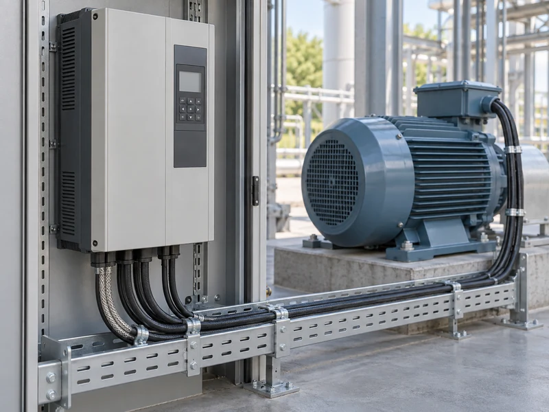
Deceleration needs its own review because the energy flow and process effects can differ from acceleration. Include the stopping requirement and any frequent reversing sequence in the enquiry. Do not assume that a successful acceleration calculation automatically validates every other motion in the cycle.
What Should Be Tested During Commissioning?
Test the agreed cycle under representative load and initial conditions within the approved commissioning procedure. Record commanded and achieved speed, relevant electrical observations, cycle timing, and available temperature data. An unloaded ramp verifies only part of the requirement when the installed load contributes substantial inertia or resistance.
Repeat the cycle as agreed to assess the required operating pattern rather than demonstrating a single isolated event. The number and sequence of repetitions should come from the duty specification and supplier guidance. Any departure from the planned load or cooling condition should be documented with the result.
If the achieved ramp differs from the requirement, preserve the observations before changing several settings at once. Determine whether the limitation arises from the mechanical model, available current, voltage, control configuration, or process conditions. This creates a more useful corrective action than repeatedly shortening the commanded ramp until a fault appears.
What Should the Supplier Receive Before Selection Is Approved?
Provide a time-based duty sheet, the inertia calculation, the load-torque description, and the required speed range. Include the supply and inverter information and state which values remain estimates. The Leili industrial applications overview can support the discussion of the intended equipment and integration scope.
Request confirmation of continuous duty, temporary demands, and the required repetition pattern as separate items. Ask for any restrictions that must be preserved in the machine controls. This gives the commissioning and maintenance teams a clear basis for deciding whether a later production change remains within the original selection.
The final record should explain why the chosen motor and drive meet the motion requirement. Retain the calculation and test evidence together, because either one alone can leave an important question unanswered. A well-specified acceleration duty turns a vague request for more power into a reviewable requirement for the complete machine.