
A hybrid stepper motor drawing requires more than checking its frame size. Seven mechanical dimension groups determine whether the motor fits the mounting bracket and connects correctly to the driven mechanism.
Before approving a supplier drawing, designers should verify mounting interfaces, shaft geometry, accessory clearances, and cable routing. These checks help prevent assembly conflicts and unnecessary revisions.
Mounting Pilot Diameter and Depth
The mounting pilot establishes the motor’s radial locating interface with the machine bracket. Its diameter and depth determine how the motor enters the locating bore and seats against the mounting surface.
Check Pilot Diameter and Bracket Bore Compatibility
The pilot diameter must match the corresponding bracket bore according to the intended locating fit. A clearance fit may allow easier assembly, while a closer fit can provide more repeatable radial positioning.
Designers should avoid selecting the bracket bore using only the nominal motor diameter. The tolerance ranges of both components determine the actual clearance or interference after manufacturing.
For example, if the motor pilot approaches the upper end of its permitted diameter range while the bracket bore approaches its lower limit, assembly may become difficult. The opposite combination can produce excessive clearance.
Verify Pilot Depth and Mounting-Face Contact
Pilot depth determines how far the locating feature extends into the bracket. The bracket bore must accommodate this projection without preventing the motor mounting face from contacting its intended seating surface.
A pilot that bottoms inside a shallow bore can leave a gap between the mounting faces. Even when the bolt holes align, the motor may not seat correctly against the bracket.
This condition can affect positioning, mounting stability, and heat transfer through the interface. Where the mounting bracket acts as a thermal path, incomplete contact can also reduce the available heat-flow area.
The mounting face should serve as the primary axial datum for evaluating pilot depth. The pilot axis provides a useful radial reference for subsequent hole-pattern and shaft-position checks.
Select Appropriate Inspection Methods
A micrometer is suitable for checking accessible external pilot diameters when its resolution and uncertainty meet the drawing requirement. A bore gauge can evaluate the corresponding bracket locating bore.
Depth measurements may require a depth micrometer or another instrument capable of referencing the actual mounting face. Calipers are useful for preliminary checks but may not provide sufficient accuracy for every specified tolerance.
Bolt-Hole Pattern and Usable Thread Depth
Confirm Hole Count and Hole-Pattern Geometry
Start by checking the number of mounting holes and their arrangement around the motor body. Verify the center-to-center distances, angular relationships, and bolt-circle dimensions where applicable.
The hole pattern should be referenced to the mounting pilot axis and mounting face. This creates a consistent relationship between the locating interface and fastening features.
A bolt circle alone may not fully describe a pattern when the holes have a specific angular orientation. Where orientation matters, the drawing should also define the relevant angular position or coordinate locations.
Distinguish Drilled Depth from Usable Thread Depth
The drilled depth includes the complete hole produced by the drilling operation. Its bottom may contain a conical drill point or another non-threaded region.
Usable thread depth describes the axial length over which the specified internal thread is properly formed and available for fastener engagement. It excludes incomplete threads and other regions that cannot provide the intended engagement.
For a blind threaded hole, the selected screw must not bottom out before the motor mounting face is properly clamped. The screw length should account for bracket thickness, washers, clearances, and the actual threaded region.
Review Hole Position and Fastener Access
For example, a small positional deviation in each mating component can accumulate in the direction that reduces available bolt clearance. The assembly may become difficult even when both components individually meet their drawings.
Check whether the fastening arrangement allows normal tool access. Nearby housing features, bracket walls, recesses, and surrounding machine components can obstruct a socket, wrench, or other required installation tool.
For inspection, pin gauges can check suitable hole diameters, while thread gauges verify thread characteristics. Coordinate measuring equipment or dedicated fixtures can evaluate hole positions when the specified tolerance requires it.
Shaft Diameter and Mating Fit
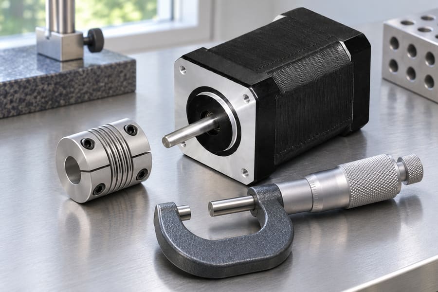
Match Shaft Diameter to Coupling Bore
Do not select a coupling based only on the nominal shaft diameter. The actual fit depends on the dimensional limits of both the shaft and coupling bore.
If the coupling uses a clamping mechanism, verify that its specified clamping range accommodates the shaft tolerance. Do not assume that a coupling described by a nominal bore size automatically fits every shaft within an unspecified range.
Check Shaft-End Chamfers and Fillets
The shaft shoulder may also include a fillet where the shaft transitions to a larger diameter. A coupling with a square internal corner can interfere with this fillet before reaching its intended axial position.
Distinguish Diameter Accuracy from Geometric Runout
A shaft can meet its diameter tolerance while still exhibiting geometric runout. These characteristics describe different aspects of the manufactured shaft.
If the coupling or driven equipment requires controlled runout, specify the applicable geometric requirement separately. Do not assume that a close shaft diameter tolerance automatically guarantees concentricity.
Use an outside micrometer to measure shaft diameter at appropriate axial and circumferential locations. For specified geometric requirements, select a suitable indicator setup or coordinate measurement method.
Shaft Projection and Usable Coupling Engagement
Shaft projection describes how far the shaft extends beyond the motor mounting face or another specified reference surface. Usable coupling engagement describes how much of that projection can actually enter the coupling hub.
Establish the Shaft Projection Reference
Confirm whether the specified length ends at the shaft tip, the end of a particular cylindrical section, or another defined feature. Ambiguous dimension endpoints can lead to different interpretations during manufacturing and inspection.
Calculate Actual Usable Engagement
Exclude the shaft-end chamfer from the available full-diameter engagement. Also account for shoulder fillets, reduced-diameter sections, relief grooves, and any other features that cannot provide the intended contact.
For example, a coupling with a deep bore may still provide limited usable engagement if an internal step prevents the shaft from reaching the full bore depth. Conversely, a shaft may bottom against the coupling interior before its intended engagement position.
A practical review should identify the minimum intended engagement and the maximum insertion depth permitted by the complete geometry. These are separate checks and should not be replaced by one nominal length.
Review the Axial Tolerance Stack
For a conservative worst-case assessment, add the individual dimensional deviations in the direction that reduces engagement. Separately assess the opposite direction, which may increase insertion and create a bottoming or interference condition.
Do not automatically assume that positive and negative deviations cancel each other. Such statistical assumptions require a justified production and process basis.
A depth micrometer, height gauge, or suitable fixture can verify shaft projection. Assembly checks may then confirm the actual engagement position using the specified coupling geometry.
Shaft Flats/Keyways and Their Axial Position
Flats and keyways provide mechanical features for torque transmission or coupling retention. Their dimensions and positions must match the selected coupling design rather than being treated as secondary shaft details.
Verify Flat and Keyway Dimensions
For a shaft flat, confirm the flat width, depth, and relationship to the original shaft diameter. A flat changes the local shaft profile, so the nominal diameter alone cannot describe the remaining geometry.
Across-flat measurement and flat depth are not interchangeable. Across-flat measurement describes the distance between specified opposing surfaces, whereas flat depth describes how far the flat extends into the original cylindrical profile.
For a keyway, specify its width and depth along with the intended key interface. The drawing should also make clear whether the depth is measured from the original shaft surface or another defined reference.
Confirm Axial Position and Feature Length
The flat or keyway must occupy the correct axial region of the shaft. Its position should be referenced to a defined shoulder, shaft end, or mounting-face datum.
Check the feature length against the coupling hub length and the intended clamping or key engagement area. A correctly sized feature can still be unusable if it falls outside the coupling’s working region.
For a coupling secured by a radial set screw, verify that the screw contacts the intended flat rather than an adjacent curved surface. Also check whether the screw location conflicts with the shaft-end chamfer or shoulder fillet.
For a keyed connection, confirm that the keyway extends far enough to support the intended key engagement. The key should not interfere with the hub’s internal geometry or extend into an unintended clearance region.
Inspect Feature Geometry with Suitable Instruments
Depth micrometers, profile measurement equipment, and suitable gauges may provide better control for more demanding dimensions. Keyway width can be checked with appropriate gauges or dimensional measurement equipment.
Where the axial position is tightly controlled, use a height gauge, coordinate measuring equipment, or a fixture referenced to the specified datum.
Body Length and Rear Accessory Envelope
A drawing review should therefore distinguish the motor body, rear cover, shaft projection, and optional accessory dimensions. Combining them into one overall length without clear endpoints can make installation planning difficult.
Confirm Motor Body Length
Identify the axial reference surfaces used to define body length. The drawing should make clear whether the measurement begins at the front mounting face and ends at the rear housing surface.
Check the relationship between body length and the available machine space. A bracket may accommodate the mounting face while an adjacent panel or enclosure prevents the motor from reaching its final position.
Account for Optional Accessories
Hybrid stepper motor configurations may include additional features depending on the application. Lead screws, encoders, and brakes should be treated as optional configurations that require confirmation during specification and ordering.
An encoder may increase the rear axial length and introduce additional connector or cable requirements. A brake may change the rear housing envelope and require additional installation clearance.
A lead screw changes the output-side arrangement and can extend the assembly beyond a conventional shaft configuration. Its overall length, support arrangement, and connection requirements must be evaluated separately.
Leili Motor provides frame, shaft, and winding customization, while accessory selection should be confirmed separately. Designers can review the available hybrid stepper motor options when defining the required motor configuration.
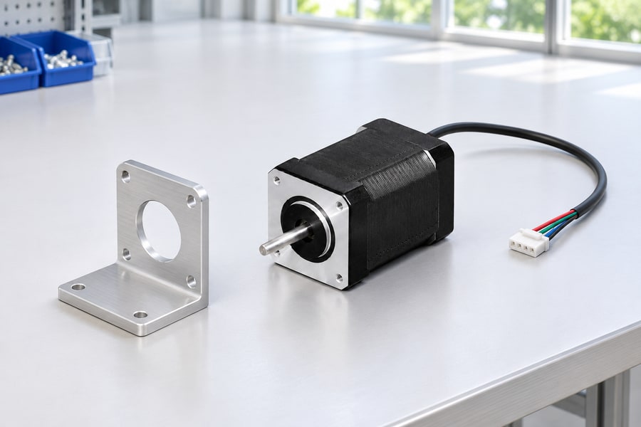
Check Tooling Access and Maintenance Clearance
Consider the actual tool approach direction. A screw may be physically accessible but impossible to tighten with the intended tool because the handle or socket cannot move through the required arc.
Where accessories are removable, allow sufficient space for their removal without dismantling unrelated machine components. This can influence panel openings and bracket geometry.
Connector and Cable Service Envelope
Connector and cable dimensions determine whether electrical connections can be installed and maintained within the available machine space. A motor can fit mechanically while its connector remains inaccessible or its cable conflicts with nearby components.
Verify Connector Position and Orientation
Confirm the connector’s location relative to the mounting face, motor centerline, and relevant housing features. Its position should be sufficiently defined to reproduce the intended assembly orientation.
Check whether the connector orientation is fixed or configurable. A connector rotated toward a bracket wall may create an assembly problem that is not apparent from a front-view drawing.
Evaluate Cable Exit and Bending Clearance
Check the cable’s specified minimum bending radius where applicable. The available space should accommodate the cable diameter, bend geometry, and routing direction.
Consider whether the cable moves during operation or remains stationary after installation. Moving arrangements may require different routing provisions from fixed installations.
The service envelope should account for the complete cable path rather than measuring only the distance from the connector to the nearest obstacle. Cable retention and strain-relief arrangements may also affect the required space.
Preserve Connector Access for Maintenance
Review the actual insertion and removal direction. If a connector requires axial withdrawal, the enclosure must provide enough room for that movement.
Also consider the access needed to release locking features or operate connector retention mechanisms. These requirements can be more restrictive than the connector’s static dimensions.
Supplier Drawing Release Checklist
Distinguish Size, Position, Orientation, and Runout
These controls should be specified according to actual functional requirements. Adding geometric tolerances without identifying the relevant datum structure can create inspection ambiguity rather than improve drawing clarity.
| Control type | What it specifies | Typical drawing application | Suitable inspection approach |
| Size tolerance | Permitted dimensional variation | Pilot diameter, shaft diameter, hole diameter | Micrometer, bore gauge, or suitable dimensional gauge |
| Position tolerance | Feature location relative to datums | Bolt-hole pattern, connector location | Coordinate measuring equipment or dedicated fixture |
| Orientation tolerance | Angular relationship between features | Mounting-face perpendicularity, surface parallelism | CMM, surface plate, or suitable indicator setup |
| Runout tolerance | Surface variation relative to a datum axis during rotation | Shaft cylindrical surface | Dial indicator with an appropriate rotational reference setup |
Match Inspection Instruments to the Requirement
| Drawing requirement | Recommended inspection method | What the inspection should establish |
| Pilot diameter | Outside micrometer | Actual external diameter |
| Pilot depth | Depth micrometer | Projection from the mounting-face datum |
| Bracket bore | Bore gauge | Internal diameter and relevant bore condition |
| Thread specification | Thread plug gauge | Thread conformity |
| Usable thread depth | Depth measurement and suitable thread verification | Available full-form threaded engagement |
| Bolt-hole position | CMM or dedicated fixture | Hole location relative to datums |
| Shaft diameter | Outside micrometer | Diameter at specified measurement locations |
| Shaft projection | Depth micrometer or height gauge | Axial extension from the defined reference |
| Flat or keyway geometry | Suitable gauges, micrometer, or CMM | Width, depth, and axial position |
| Shaft runout | Dial indicator and appropriate reference setup | Surface variation relative to the established datum axis |
Inspection reports should identify the measured characteristic, reference datum, instrument, and result. If a measurement is close to an acceptance boundary, the measurement method and uncertainty deserve particular attention.
Release the Matched Motor and Bracket Drawings
Before releasing the hybrid stepper motor drawing for production, confirm the following items:
- Mounting interface:
Pilot diameter, depth, seating contact, and bracket compatibility are defined. - Fastening:
Hole pattern, thread specification, usable thread depth, and tool access are verified. - Output shaft:
Diameter, mating fit, chamfer, fillet, and coupling compatibility are confirmed. - Coupling engagement:
Shaft projection, usable engagement, and limiting axial tolerance combinations are checked. - Shaft features:
Flat or keyway dimensions and axial positions match the coupling design. - Installation envelope:
Body length, rear accessories, connector protrusion, and maintenance clearances match the ordered configuration. - Inspection requirements:
Datums, dimensional tolerances, geometric controls, and appropriate inspection methods are documented.
The approved drawing should represent the actual motor configuration and its intended mechanical interfaces. Leili Motor’s stepper motor configurations can be considered when coordinating the required frame, shaft, and winding specifications.
Unresolved dimensions should be clarified before production release, particularly where they affect mounting-face contact, coupling engagement, or accessory clearance. A coordinated review of the motor and mating-component drawings provides a more reliable basis for mechanical approval.