
Coil resistance is a key electrical specification for miniature permanent magnet stepper motors. It should be defined by nominal resistance, reference temperature, allowable tolerance, winding configuration, and exact measurement terminals.
An incomplete resistance value can cause incorrect driver selection and inconsistent incoming inspection. Buyers should also consider measurement methods, operating temperature, winding inductance, and the motor’s intended electrical duty.
What Does Coil Resistance Mean in a Miniature PM Stepper Motor?
Coil resistance describes the opposition that a motor winding presents to direct current. For a miniature permanent magnet stepper motor, it is an important parameter for electrical matching, current estimation, and production inspection.
However, a resistance value is meaningful only when its electrical measurement path is clearly identified. The resistance of one winding section may differ from the value measured across the motor’s external terminals.
Winding Resistance vs Terminal-to-Terminal Resistance
Winding resistance refers to the DC resistance of a defined coil or winding section. Terminal-to-terminal resistance describes the complete electrical path between two specified external connection points.
These values may differ because the measured path can include multiple winding sections, internal connections, common terminals, and external lead wires.
How Winding Topology Affects Resistance
Miniature PM stepper motors may use different winding arrangements depending on their electrical design. Bipolar and unipolar configurations require particular attention because their accessible winding terminals and current paths can differ.
In a bipolar arrangement, the driver typically energizes the winding through its two ends, reversing current direction as required. A unipolar arrangement may use a center-tapped winding, allowing different winding sections to be energized.
For a center-tapped winding, full-winding resistance and half-winding resistance must be specified separately. The half-winding value should not be treated as interchangeable with the complete winding value.
Series and parallel connections can also change equivalent resistance when the motor is specifically designed to support those configurations. Buyers should not assume that every miniature motor permits reconnection.
Identify the Exact Phase and Terminal Pair
A resistance specification should identify the relevant phase and terminal pair using the approved wiring diagram.
For example, a two-phase motor might have separate phase A and phase B winding connections. The drawing should identify the corresponding pin pairs rather than simply state that resistance is measured across the motor connector.
How Should Reference Temperature and Resistance Tolerance Be Specified?
Because copper’s electrical resistance varies with its thermal condition, every specified coil resistance must be tied to a stated temperature. Without this reference, two measurements may differ even when the winding construction is identical.
Reference temperature and resistance tolerance are separate requirements. The former establishes the measurement condition, while the latter defines the acceptable deviation from the nominal value.
Define the Reference Temperature
Every nominal resistance value should include a specified reference temperature, expressed in degrees Celsius.
The motor should be unpowered and allowed to stabilize at the specified ambient condition before measurement. This helps the winding approach thermal equilibrium with its surroundings.
The reference temperature is not necessarily the motor’s operating temperature. It is the agreed condition under which the nominal resistance and its tolerance are evaluated.
For incoming inspection, buyers should establish a consistent stabilization procedure. Motors arriving from storage, transportation, or previous operation may have winding temperatures different from the inspection environment.
Establish Nominal Resistance and Tolerance
Nominal resistance defines the intended electrical value, while tolerance establishes the permitted manufacturing variation.
A complete requirement should specify the nominal value in ohms (Ω) and an acceptable minimum and maximum. Alternatively, it may use a clearly defined percentage tolerance.
For illustration only, a hypothetical winding specification might state 100 Ω with a tolerance of ±10% at 20°C. This would establish an acceptable range of 90–110 Ω under the specified measurement conditions.
These figures are illustrative, not universal requirements or published product ratings. Actual limits should follow the motor design, driver requirements, thermal conditions, and agreed production capability.
Tolerance should also be distinguished from phase balance. Two windings can individually satisfy their resistance limits while exhibiting a difference that exceeds the buyer’s separate phase-balance requirement.
Apply the Copper Temperature Coefficient
Copper resistance increases as temperature rises. An approximate linear relationship can be used to estimate resistance at another temperature:
R_T = R_ref × [1 + alpha_ref × (T − T_ref)]
R_T is resistance at temperature T. R_ref is resistance at the specified reference temperature T_ref.
Use alpha_ref for the winding conductor at the chosen reference temperature. For copper near a 20°C reference, approximately 0.00393 per °C is commonly used.
The coefficient must correspond to the selected reference temperature. When greater accuracy is required, the applicable material data and temperature range should determine the correction method.
This equation provides an estimate rather than a direct measurement. It should not replace actual winding temperature verification when evaluating thermal performance.
How Should Coil Resistance Be Measured and Inspected?
Resistance measurement procedures should be consistent with the motor’s resistance level and the required acceptance tolerance. Miniature windings can be particularly sensitive to test-lead resistance, contact quality, and measurement-induced heating.
Before measuring, the motor should be unpowered, electrically isolated from the driver, and stabilized at the specified reference temperature.
Two-Wire Resistance Measurement
Two-wire measurement is a common method for checking winding resistance. The instrument uses the same pair of leads to supply test current and measure the resulting voltage.
Its main limitation is that the displayed resistance can include contributions from test leads and contact resistance. These contributions become proportionally more significant when the winding resistance is relatively low.
The test boundary must also be clear. If measurement takes place at the connector, the result may include connector contacts and attached motor leads, depending on the connection arrangement.
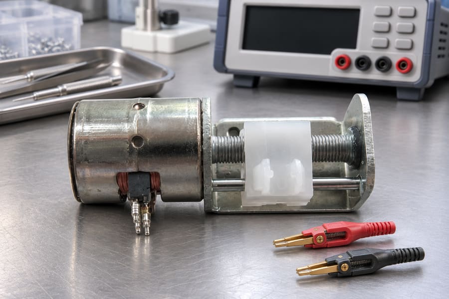
Four-Wire Kelvin Measurement
Four-wire Kelvin measurement separates the current-carrying connections from the voltage-sensing connections.
The outer connections supply the test current, while the inner connections measure voltage across the defined sense points. This arrangement reduces the influence of resistance in the current-carrying test leads.
An important distinction is that Kelvin measurement does not automatically remove the resistance of every motor lead. Any motor lead, connector section, or internal conductor located between the defined voltage-sensing points remains part of the measured resistance.
For example, sensing directly at the motor winding terminals can exclude external test-lead voltage drops. Sensing at the far end of an attached motor cable includes the cable section between those sense points.
Control Test Current and Measurement Conditions
The winding should be measured using a suitably low test current. Excessive current can heat the copper and change the resistance during measurement.
This effect is particularly important when measuring small windings or repeating measurements over short intervals. A rising reading may reflect thermal drift rather than a manufacturing difference.
Measurement duration should be controlled, and the instrument should use a suitable current range. The winding should remain disconnected from external drive electronics throughout the resistance test.
Contact pressure, terminal cleanliness, and connection repeatability also influence measurement quality. These factors should be controlled when establishing a production inspection procedure.
Measurement Pitfalls and Corrective Checks
| Measurement pitfall | Possible effect | Recommended check |
| Unstable winding temperature | Resistance readings vary | Apply a controlled ambient soak |
| Excessive test current | Self-heating and resistance drift | Use an appropriate low test current |
| Long or resistive test leads | Increased two-wire readings | Evaluate four-wire measurement |
| Incorrect terminal pairing | Measures the wrong winding path | Verify the wiring diagram |
| Undefined cable boundary | Inconsistent lead inclusion | Mark voltage-sensing points |
| Poor electrical contacts | Unstable or elevated readings | Clean and secure connections |
| Instrument uncertainty | Unreliable tolerance assessment | Verify calibration and measurement capability |
| Repeated measurements without stabilization | Results reflect thermal changes | Allow readings and temperature to settle |
Record and Evaluate Measurement Results
Production inspection records should identify the motor model, lot number, winding phase, terminal pair, measurement method, and test conditions.
Individual readings should be retained instead of recording only an average. This allows engineers to evaluate variation between samples and identify possible phase imbalance.
The measurement system should have sufficient resolution and accuracy for the agreed acceptance limits. Measurement uncertainty should be considered when defining borderline acceptance and retesting procedures.
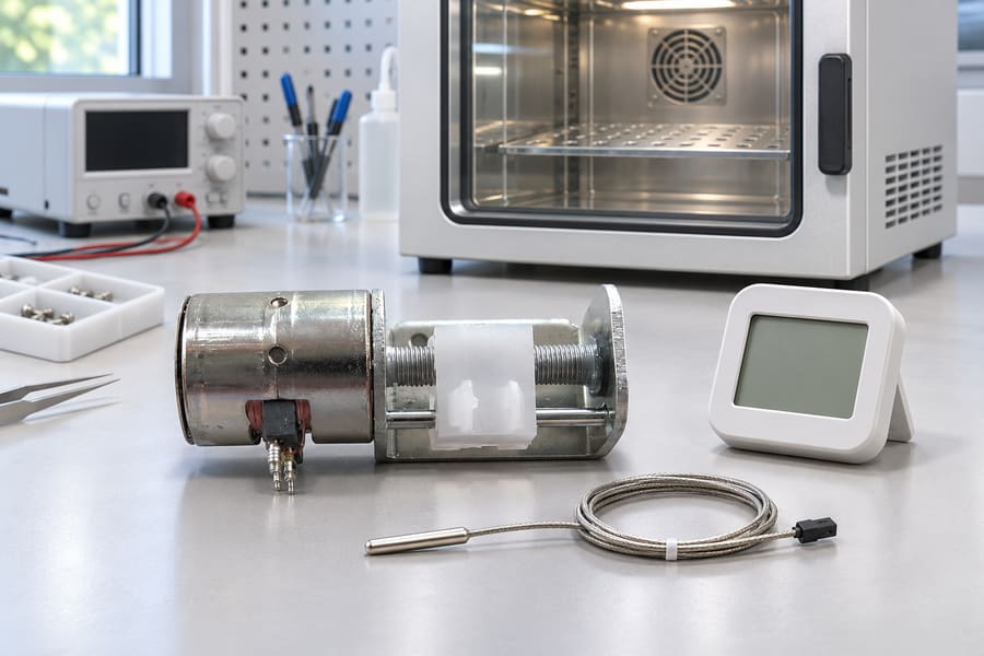
How Does Operating Temperature Change Coil Resistance?
A resistance value measured under controlled conditions does not remain constant throughout motor operation. Copper winding temperature changes as electrical losses generate heat during energization.
Cold Resistance vs Operating-Temperature Resistance
Cold resistance describes the winding resistance measured at the specified reference condition before normal operation raises its temperature.
During operation, current passing through the winding produces copper losses. These losses increase winding temperature, which subsequently increases electrical resistance.
A motor operating intermittently may experience different thermal conditions from one energized continuously. Therefore, resistance specifications should not be interpreted without considering the intended duty cycle.
Buyers should also distinguish winding temperature from ambient temperature. A motor installed in a warm enclosure may operate at a higher winding temperature than one exposed to better cooling conditions.
Estimate Resistance at Operating Temperature
The copper temperature relationship introduced earlier can estimate resistance at an elevated winding temperature.
Consider a hypothetical winding with a reference resistance of 100 Ω at 20°C. Using an approximate copper coefficient of 0.00393 per °C, its estimated resistance at 80°C would be approximately 123.6 Ω.
This example illustrates temperature-related resistance change only. It does not represent a Leili Motor product rating or establish a recommended operating temperature.
When comparing calculated and measured values, engineers should ensure that both refer to the same electrical measurement path. Otherwise, differences may result from lead inclusion or winding configuration rather than temperature.
Understand the Electrical and Thermal Consequences
Copper losses can be expressed as:
P_Cu = I_rms² × R
P_Cu is average copper loss in the measured winding path. Use its RMS current and resistance at the relevant operating temperature; sum the phase losses when evaluating the whole motor.
At constant current, increasing resistance increases copper losses. Under approximately constant-voltage excitation, however, increasing resistance generally reduces steady-state current.
Thermal performance also depends on mounting conditions, surrounding materials, ventilation, enclosure design, and energization duration. Resistance alone cannot establish the permissible continuous current or maximum winding temperature.
How Does Coil Resistance Affect Stepper Motor Driver Compatibility?
Voltage-driven and current-regulated systems respond differently to resistance changes. Understanding this distinction helps designers avoid selecting a motor based on nominal resistance alone.
Resistance in Voltage-Driven Applications
In a simplified steady-state DC model, current is related to applied voltage and winding resistance:
I = V / R
For the same applied voltage, a lower winding resistance generally produces higher steady-state current. A higher resistance produces lower current under otherwise equivalent conditions.
This relationship provides a basic estimate, but it does not fully describe a stepper motor during switching operation. Winding inductance and back electromotive force also influence current behavior.
Temperature changes must also be considered. As copper resistance rises, steady-state current under approximately constant-voltage excitation tends to decrease.
Resistance in Current-Regulated Applications
A current-regulated driver controls winding current by adjusting its applied voltage. This allows the driver to maintain a commanded current within its electrical operating limits.
However, current regulation does not make winding resistance irrelevant. Resistance determines part of the voltage required to maintain the commanded current and contributes directly to copper losses.
The driver must also have sufficient voltage headroom to overcome winding inductance and back electromotive force during operation.
If the driver reaches its voltage limit, the actual winding current may fall below the commanded value. Consequently, the motor may not deliver the expected dynamic performance.
Consider Winding Inductance and Dynamic Current
Resistance and inductance describe different electrical characteristics. Winding resistance determines the sustained voltage drop and associated copper heating, whereas inductance governs the rate at which current builds or decays.
The available supply voltage, driver control strategy, stepping frequency, and winding inductance all influence current rise. These factors become especially important when the motor operates at higher speeds.
A motor with suitable nominal resistance may still be unsuitable for an application if its inductance prevents adequate current buildup under the available driver voltage.
Why Resistance Alone Cannot Predict Torque
Motor torque depends on more than winding resistance. Phase current, winding turns, magnetic circuit characteristics, rotor construction, and operating conditions all influence electromagnetic performance.
Holding torque describes performance under a stationary energized condition. Running torque depends on the motor’s actual electrical and mechanical operating conditions.
Two motors with similar winding resistance may therefore exhibit different torque characteristics because their magnetic and winding designs differ.
Resistance matching should be treated as an electrical compatibility check, not a direct torque prediction. Buyers should request relevant motor performance data and evaluate it under the intended driver and operating conditions.
What Should Buyers Include in a Coil Resistance Specification and Acceptance Plan?
A useful resistance specification translates electrical design requirements into measurable purchasing and inspection criteria. It should eliminate ambiguity between the motor drawing, supplier production process, and incoming quality inspection.
Prepare a Complete Resistance Specification
Phase balance should be specified separately from individual resistance tolerance. If both phases must satisfy individual limits and a phase-to-phase difference limit, the drawing should state both acceptance requirements.
The measurement boundary should identify whether the test includes the motor’s attached leads and connector. For four-wire measurements, the voltage-sensing locations should be clearly defined.
A practical hypothetical drawing callout could read:
Phase A winding resistance: 100 Ω ±10% at 20°C; measured with Kelvin sense probes on the motor-side metal surfaces of connector pins 1 and 2; include the winding and internal leads between these points, excluding the mating cable and external test leads; procedure: unpowered and isolated winding, stabilized at reference temperature, measured using a low-current four-wire method.
All numerical values in this example are hypothetical. The tolerance is illustrative rather than a universal recommendation.
The actual drawing should also provide a separate phase-balance requirement where needed. The acceptable threshold should be jointly established by the purchaser and manufacturer, taking the motor’s construction and intended operating conditions into account.
| Specification field | Acceptance information to agree |
| Winding path | Phase, terminal pair, topology and wiring revision |
| Nominal resistance | Ohms, minimum/maximum or percentage tolerance |
| Reference condition | Winding temperature and stabilization procedure |
| Measurement boundary | Sense points and included internal leads or contacts |
| Test procedure | Instrument method, test current, duration and settling |
| Phase balance | Separate limit and calculation convention, where required |
| Lot inspection | Sampling, traceability and retained individual readings |
| Borderline results | Uncertainty, retest and nonconformance disposition |
Establish Production Lot Inspection Requirements
Production inspection should follow the same electrical configuration and measurement boundary established in the approved drawing.
The inspection plan should identify sampling quantity, inspection frequency, instrument requirements, and recording procedures. These details help ensure that different production lots are evaluated consistently.
Ambient stabilization should be controlled before measurements begin. The inspection procedure should also define the test current and measurement duration to limit self-heating.
Each result should be traceable to its motor model, production lot, and measured phase. Individual readings should be retained to support variation analysis and nonconformance investigations.
Where measurements approach an acceptance boundary, the agreed procedure should address measurement uncertainty, repeat testing, and disposition. All valid test readings must be retained and evaluated; results should never be filtered simply because some fail to meet expectations.
Verify Published Product Information and Customization Requirements
Published product information can help buyers identify available motor configurations and potential customization requirements. However, listed resistance values should not automatically be treated as complete electrical acceptance specifications.
Leili Motor provides miniature permanent magnet stepper motor options, including coil-resistance and shaft customization. Buyers can review the miniature permanent magnet stepper motor range when identifying suitable motor configurations.
The 065BY25T product range also lists miniature PM screw-motor variants with different winding resistance values. These differences provide a useful starting point when comparing electrical configurations.
The 065BY25T PM stepper motor variants can help buyers identify available resistance options for further technical evaluation.
However, the published information does not establish the reference temperature or allowable resistance tolerance. Buyers should request these details rather than assume that listed values represent guaranteed production acceptance limits.
Finalize the Supplier Handover
Before approving a motor specification, buyers and suppliers should confirm that the electrical drawing and inspection procedure describe the same winding path.
Finally, the supplier should provide traceable inspection records showing individual phase measurements and conformity with the agreed acceptance criteria.