
A PM stepper linear mechanism needs the right component restrained against rotation. Locking the wrong member stops the intended motion; leaving the translating member free to turn can prevent useful linear travel.
Identify the screw-and-nut arrangement first, then choose a restraint that permits translation. Its torque path, clearance and alignment must remain effective throughout the usable stroke.
Understand the Two Operating Architectures of PM Stepper Linear Mechanisms
Before designing an anti-rotation mechanism, identify which component rotates and which component translates. PM stepper linear mechanisms commonly use two arrangements, each requiring a different restraint location.
Rotating-Nut and Nonrotating-Translating-Screw Design
In a rotating-nut configuration, the motor drives a threaded nut while the lead screw remains restrained against rotation. The nut’s rotation produces axial movement through the threaded interface.
The screw therefore needs an anti-rotation feature that reacts the torque generated during operation. At the same time, the restraint must allow the screw to move freely along its intended axis.
This arrangement requires two distinct mechanical conditions. The screw must resist angular movement while maintaining sufficient freedom for linear displacement throughout the operating stroke.
A guided carriage, keyed sleeve, or another suitable mechanical feature can provide this restraint. Its connection to the supporting structure establishes the reaction path for rotational forces.
The axial connection must also transmit the intended thrust to the external load. Depending on the design, suitable compliance may accommodate minor alignment differences without allowing unwanted rotation.
Rotating-Screw and Moving-Nut Design
A rotating-screw configuration works differently. The motor rotates the lead screw, and the threaded nut travels along the screw as the threads convert rotation into linear displacement.
In this arrangement, the screw must remain free to rotate. The moving nut or its attached carriage requires appropriate rotational restraint so that it follows the intended linear path.
Locking the screw in this configuration would prevent normal operation. The anti-rotation feature must instead react torque at the moving nut or carriage while allowing axial translation.
The supporting guide may also control the carriage’s orientation and react external forces. However, its design must account for the actual torque and loading transferred through the assembly.
Identify the Architecture Before Applying Anti-Rotation Measures
The two configurations can appear similar from the outside, particularly in compact motor assemblies. Their internal mechanical relationships, however, determine where the restraint belongs.
An assembly drawing or cross-sectional view should identify the motor output, threaded engagement, rotating member, translating member, and supporting structure.
Product descriptions and photographs provide useful external information but cannot always establish the internal screw-and-nut arrangement. Confirming the actual construction prevents incorrect modifications.
For applications involving permanent magnet stepper motors, the motor configuration and mechanical transmission should be considered together. The motor’s operating principle alone does not establish which component must remain stationary rotationally.
Distinguish Anti-Rotation Restraint from Mechanical Load Guidance
Anti-rotation and linear guidance are related mechanical functions, but they solve different problems. Treating them as interchangeable can introduce unwanted forces and reduce the reliability of a linear mechanism.
What Does an Anti-Rotation Mechanism Actually Do?
An anti-rotation mechanism prevents a designated component from turning when its intended movement is translation. It provides a mechanical reaction against torque generated during operation.
For a nonrotating screw, this restraint reacts the torque acting on the screw while permitting axial travel. For a moving-nut arrangement, it controls the nut or carriage instead.
The restraint must transfer reaction torque into a supporting structure. Its mounting connections therefore need sufficient mechanical integrity to prevent unwanted angular displacement under the intended operating conditions.
Anti-rotation does not necessarily mean that the restrained component cannot move in any other direction. In a translating-screw design, axial freedom remains essential to normal operation.
Why a Lead Screw Should Not Automatically Serve as a Linear Guide
A lead screw primarily transmits axial force through its threaded interface. It should not automatically be treated as the supporting guide for external radial or lateral loads.
When a moving assembly experiences side forces, those forces can bend the screw or produce uneven contact between mating threads. The resulting friction may interfere with smooth movement.
A separate linear guide can support the moving assembly and control its travel path. Depending on the application, this may involve guide rods, linear rails, or an appropriately designed carriage.
The guide must be selected according to the actual load direction, mounting geometry, and movement requirements. Its purpose is not simply to prevent rotation but also to maintain the required mechanical trajectory.
Separate the Three Mechanical Functions
Three functions should be considered independently during mechanism design.
- Anti-rotation:
Prevents unintended angular movement and transfers reaction torque into the supporting structure. - Linear guidance:
Controls the moving assembly’s path and reacts applicable lateral forces. - Axial force transmission:
Transfers thrust between the motor-driven mechanism and the external load.
A single component may perform more than one function when its geometry, materials, and mounting arrangement support those responsibilities. However, combining functions should be an intentional engineering decision.
For example, a guided carriage may both maintain orientation and support side loads. Its anti-rotation capability still depends on how the carriage interacts with its guide and mounting structure.
Establish a Clear Mechanical Load Path
The rotational reaction path begins at the restrained screw or nut and continues through the anti-rotation feature into the supporting frame. Every connection along this path influences overall stiffness.
The axial load follows a different route through the threaded interface and connected mechanical components. These forces should not be transferred unintentionally through components designed only for rotational restraint.
Mounting flexibility and connection geometry also affect alignment. A poorly arranged load path can introduce bending moments or unwanted friction even when the individual components appear correctly sized.
Where alignment accommodation is necessary, a connection with suitable lateral or angular accommodation may help prevent overconstraint. It must retain the required axial stiffness and force capacity; the designed torque-reaction path must remain continuous, whether through that connection or a separate restraint.
Compare Practical Methods for Preventing Unwanted Rotation
Several mechanical arrangements can prevent unwanted rotation in PM stepper linear mechanisms. Their suitability depends on the component being restrained, available space, stroke length, and required load transfer.
Guided Carriage and Linear Guide
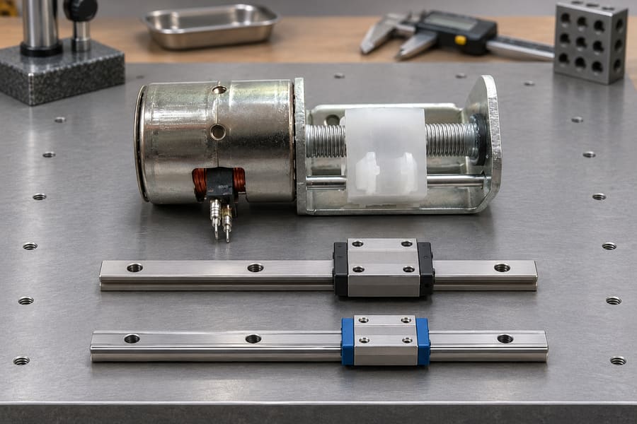
A guided carriage provides a defined path for the translating component. Its engagement with a supporting guide can resist angular movement while permitting the intended linear displacement.
In a rotating-nut design, the carriage may connect to the nonrotating screw or its associated moving assembly. In a rotating-screw design, it may restrain the translating nut.
Guide geometry determines how rotational reaction forces transfer into the mounting structure. Rail spacing, carriage engagement, and bracket stiffness can therefore influence the effectiveness of the restraint.
The guide must also accommodate external loads without forcing the lead screw to act as an unintended lateral support. This separation helps reduce unnecessary bending and friction.
Alignment is particularly important when the screw and guide operate in parallel. If their relative positions are incorrect, the assembly may become mechanically overconstrained during translation.
Keyed or Splined Sliding Sleeve
A keyed sleeve provides rotational restraint through engagement between a key and a corresponding slot. The mating geometry transfers torque while allowing the designated component to slide axially.
A splined sleeve uses multiple mating tooth surfaces to react rotational forces. Depending on the arrangement, it can provide axial sliding while maintaining rotational engagement.
Both approaches require suitable clearance and sufficient engagement throughout the intended stroke. Excessive clearance permits unwanted angular movement, while insufficient clearance can cause binding.
The sleeve mount must be capable of carrying the operational reaction forces. A weak mounting arrangement can undermine an otherwise suitable keyed or splined interface.
Contact surfaces deserve attention because repeated sliding can gradually change their geometry. Wear may increase backlash, reduce effective engagement, or produce inconsistent movement.
Lubrication should match the materials and operating environment. The design should also consider contamination, accessibility, and the possibility of lubricant loss during extended operation.
Designed Flats and Matching Restraint Surfaces
Purpose-designed flats provide another way to react torque. A matching guide or restraint engages the flat surfaces and prevents the designated component from rotating.
This arrangement can be useful when a compact assembly has limited space for a separate carriage or sleeve. However, its effectiveness depends on contact geometry and the supporting structure.
The flat surfaces must remain properly engaged throughout the required movement. Their dimensions and clearances should account for sliding contact, manufacturing variation, and expected wear.
Designed flats are different from improvised modifications. Cutting or grinding an existing screw without an approved design can affect its strength, surface condition, and dimensional accuracy.
Working threads must never be clamped, keyed, or used as improvised anti-rotation surfaces. Such modifications can damage the thread profile and interfere with the screw-and-nut engagement.
Select the Method According to the Actual Architecture
The correct method depends first on which component requires restraint. A rotating-nut arrangement needs to restrain the translating screw, whereas a rotating-screw arrangement needs to restrain the moving nut or carriage.
Other selection factors include available mounting space, required travel, reaction torque, external loading, and maintenance requirements. The design must also accommodate the complete operating envelope.
| Anti-Rotation Method | Main Function | Movement Allowed | Important Design Consideration |
| Guided carriage | Reacts torque through the guide structure | Axial translation | Alignment and guide loading |
| Keyed sleeve | Transfers torque through mechanical engagement | Axial sliding | Engagement and clearance |
| Splined sleeve | Restrains rotation through mating spline surfaces | Axial sliding | Spline fit and wear |
| Designed flats | Reacts torque through matching contact surfaces | Depends on guide arrangement | Contact geometry and travel clearance |
No single approach is suitable for every PM stepper linear mechanism. The restraint must match the intended kinematics and provide a reliable connection to the supporting structure.
Design Anti-Rotation Components for Reliable Full-Stroke Movement
Preventing rotation at one position does not guarantee reliable operation throughout the complete stroke. The restraint must maintain its function without obstructing the required translation.
Maintain Engagement Throughout the Operating Stroke
The relative positions of the screw, nut, carriage, and restraint change as the mechanism moves. Their engagement must therefore be evaluated across the entire intended travel.
For a keyed or splined sleeve, sufficient engagement must remain available at both ends of the stroke. A restraint that partially disengages during movement may permit unwanted angular displacement.
Guided carriages also require suitable engagement with their supporting structures. Their available travel must accommodate the moving assembly without running into mounting hardware or other obstacles.
The surrounding mechanical layout matters as well. Couplings, brackets, covers, and connected components should not interfere with the restraint as its position changes.
Balance Clearance and Backlash
Sliding mechanisms require clearance to move without excessive friction. However, excessive clearance can introduce rotational play that reduces the effectiveness of an anti-rotation arrangement.
Backlash in the restraint differs from backlash in the screw-and-nut interface. Both can contribute to positioning uncertainty, but they originate from different mechanical relationships.
For example, a loose keyed sleeve may allow angular movement even when the threaded interface itself has limited backlash. Conversely, a correctly restrained screw can still exhibit movement caused by thread clearance.
Clearance should reflect the actual geometry, materials, manufacturing variation, and operating conditions. Tightening every interface as much as possible is not a reliable way to improve mechanical precision.
Account for Wear and Lubrication
Repeated sliding creates contact between mating surfaces. Over time, wear may change the clearance and contact pattern, particularly where the restraint repeatedly reacts torque.
Keyed and splined interfaces should be inspected for damaged edges, uneven contact, and changes in engagement. Guided arrangements require attention to carriage condition and guide surfaces.
Lubrication helps manage friction where the design calls for lubricated sliding contact. Its suitability depends on material compatibility, environmental conditions, and the interface’s operating requirements.
Contamination can also affect movement by entering sliding interfaces or accumulating around guide surfaces. Maintenance access should allow inspection and appropriate cleaning without disturbing critical alignment.
Prevent Overconstraint and End-Position Interference
Overconstraint occurs when multiple mechanical features restrict movement in ways that are not geometrically compatible. This can introduce internal forces even without an external load.
For example, a rigidly mounted guide and an independently misaligned screw may attempt to control the same moving assembly along slightly different paths.
Suitable connection compliance can accommodate limited alignment differences. However, compliance must not eliminate the designed torque-reaction path or allow uncontrolled axial displacement.
End-position checks are equally important. Mechanical stops should correspond to the usable stroke, and the restraint should not bottom out or become an unintended travel stop.
Electrical or programmed travel limits do not automatically prevent physical interference. The mechanical design must retain sufficient clearance for the actual movement envelope.
Troubleshoot Common Screw Rotation and Linear Movement Problems
Unexpected rotation, binding, and positioning inconsistency can originate from different parts of a linear mechanism. Troubleshooting should begin by identifying the intended motion rather than immediately changing the restraint.
The Screw Rotates When It Should Translate
If the design requires a nonrotating screw, unexpected rotation suggests that its restraint may be ineffective or incorrectly connected.
Inspect the anti-rotation feature, mounting fasteners, engagement surfaces, and supporting structure. Look for loose connections, excessive clearance, partial disengagement, or visible damage.
Also verify that the restraint remains engaged throughout the operating stroke. A mechanism may resist rotation near one position but lose effective engagement as the screw moves.
The corrective action must reflect the actual architecture. If the screw is intentionally designed to rotate, its rotation is normal and must not be eliminated.
The Mechanism Binds or Moves Unevenly
Binding may indicate insufficient clearance, guide misalignment, or incompatible mounting geometry. It can also result from an assembly that constrains the same movement through multiple rigid interfaces.
Check the relative alignment of the motor, screw, nut, guide, and supporting brackets. Small geometric differences can create additional friction during translation.
Investigate whether external loads are being transferred through the lead screw instead of an appropriate guide. Unintended lateral loading may produce bending and uneven thread contact.
Wear and contamination should also be considered. Damaged sliding surfaces or inadequate lubrication can cause movement resistance that changes across the stroke.
Excessive Backlash or Inconsistent Positioning
Rotational play in the anti-rotation mechanism should be distinguished from backlash in the threaded interface. Each requires inspection at its own mechanical connection.
For a keyed or splined restraint, examine the engagement surfaces and supporting connections. For a guided carriage, inspect the guide engagement and mounting stability.
Positioning inconsistency can also originate from other parts of the motion system. A correctly restrained screw does not automatically guarantee accurate positioning if the threaded interface or external mounting has excessive play.
| Observed Problem | Possible Mechanical Cause | Recommended Diagnostic Check |
| Screw rotates unexpectedly | Incorrect or ineffective restraint | Confirm architecture and restraint engagement |
| Binding during translation | Misalignment or insufficient clearance | Inspect guide and screw alignment |
| Excessive rotational play | Worn or loose restraint | Inspect engagement surfaces and fasteners |
| Uneven movement | Side loading or overconstraint | Check load path and guidance arrangement |
| Restricted movement near stroke ends | Interference or insufficient engagement | Inspect full-stroke clearance |
Diagnose Without Improvised Modifications
Before making adjustments, document the original assembly arrangement and identify the component responsible for the observed problem. This makes it easier to distinguish design limitations from assembly faults.
Consult the relevant drawings and manufacturer-approved adjustment procedures. Avoid drilling, cutting, welding, or clamping working components to create an unverified restraint.
If an anti-rotation feature is damaged, replacement should preserve the intended geometry and mechanical load path. A temporary modification may conceal the original problem while introducing additional friction or structural weaknesses.
Verify Anti-Rotation Performance in a PM Stepper Linear Assembly
Mechanical verification should establish that the intended component rotates or translates correctly under controlled operating conditions. It should also confirm that the restraint remains effective without restricting normal movement.
Confirm the Mechanical Configuration Before Testing
Begin with the assembly drawing and identify the rotating member, translating member, anti-rotation feature, and supporting guide. Confirm that the actual assembly matches the intended mechanical arrangement.
For a rotating-nut configuration, verify that the screw can translate while remaining restrained against rotation. For a rotating-screw configuration, confirm that the screw remains free to rotate and the moving nut receives appropriate restraint.
Inspect the mounting connections and mechanical engagement before energizing the motor. Any visible interference or incorrect assembly should be addressed before functional testing.
Perform Controlled Low-Speed Movement Checks
Start with controlled, low-speed operation to observe the basic mechanical behavior. This makes unexpected rotation, binding, and irregular translation easier to identify.
Watch the component that should remain rotationally restrained. Its angular position should remain consistent with the intended design while its permitted movement remains unrestricted.
For a rotating-screw arrangement, observe the screw’s rotation rather than treating it as a fault. Confirm that the moving nut or carriage follows the intended path.
Check movement in both directions. Reversing direction can reveal mechanical play, uneven friction, or interference that may not be apparent during one-way movement.
Check Movement Across the Complete Stroke
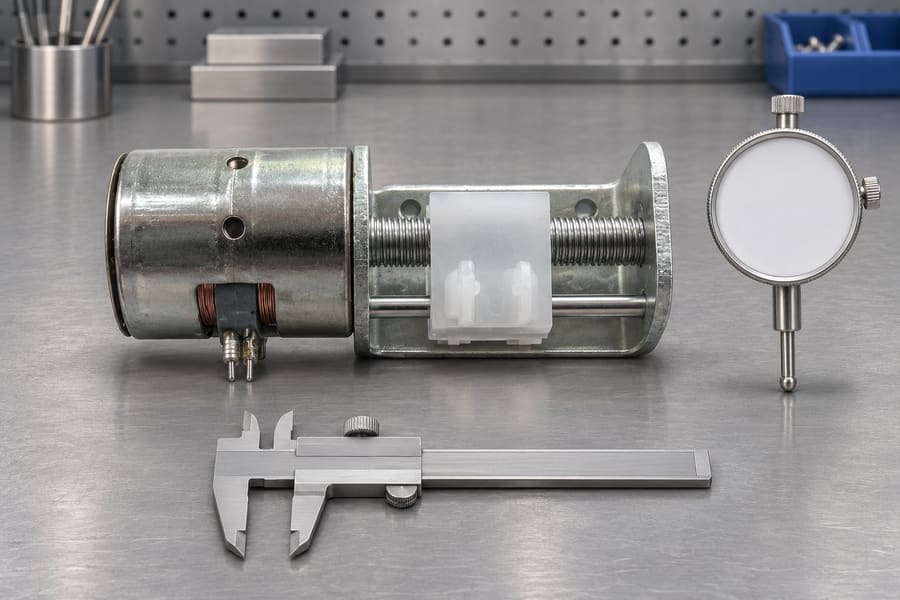
A restraint may operate correctly near the starting position but encounter problems farther along the travel. Verification should therefore include the beginning, middle, and end of the usable stroke.
Observe whether the engagement remains sufficient and whether any component approaches a mechanical obstruction. Check that the screw, nut, carriage, and surrounding structures maintain appropriate clearance.
The mechanism should move without unexpected changes in rotational restraint or axial freedom. Any unusual increase in resistance should prompt an inspection of alignment and contact conditions.
End limits should also correspond to the intended mechanical travel. Confirm that the assembly does not rely on the anti-rotation feature to absorb an unintended stopping force.
Evaluate Alignment and Representative Loading
After basic movement is established, evaluate the mechanism under representative application conditions. External forces can change the behavior of guides, mounting brackets, and mechanical connections.
Check that the restraint continues to function correctly under the specified moving load. Check for abnormal vibration, noise, friction, and visible displacement.
The evaluation should distinguish guide performance from anti-rotation performance. A guide may support the external load while the separate restraint reacts torque through another mechanical path.
Repeatability should be assessed through controlled movement cycles using application-specific acceptance criteria. Unloaded movement alone cannot establish suitability under every operating condition.
Use Product Drawings to Confirm Actual Construction
The 065BY25T PM Stepper Motor provides a relevant example of a miniature PM stepper product with a framed screw mechanism.
Its product information and available mechanical illustrations can help engineers consider motor dimensions and integration requirements. However, an external photograph does not establish the internal screw-and-nut arrangement.
The anti-rotation method, internal engagement geometry, and load paths should not be inferred from the product’s appearance. These details require appropriate technical documentation or confirmation from the manufacturer.
For engineering approval, maintain a practical acceptance record containing:
- Mechanism configuration:
Identify the rotating and translating components and their intended movement. - Restraint arrangement:
Record the anti-rotation method, mounting location, and engagement condition. - Guidance and alignment:
Document the guide arrangement and relevant alignment observations. - Travel verification:
Record movement in both directions and observations across the usable stroke. - Operating observations:
Note abnormal friction, vibration, noise, backlash, or mechanical interference. - Acceptance criteria:
Reference the agreed application requirements and any applicable manufacturer specifications.
This record provides a traceable basis for reviewing the mechanical arrangement and determining whether the assembled PM stepper linear mechanism performs as intended.