
July 30, 2026

Single Rotor vs Dual Rotor Axial Flux Motors
News

Single Rotor vs Dual Rotor Axial Flux Motors: Which Design Is Better?

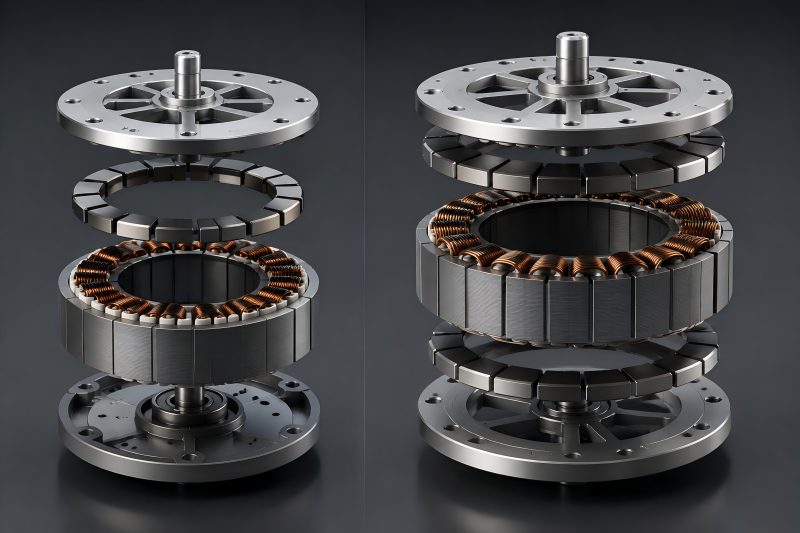
Single rotor and dual rotor axial flux motors represent two different design philosophies. The single rotor design emphasizes simplicity, cost control, and easier production, making it suitable for many commercial and industrial applications. The dual rotor design focuses on maximizing torque density, improving force balance, and supporting higher performance requirements. For applications requiring the highest power density within limited space, the dual rotor structure has clear advantages. However, for large-scale manufacturing where reliability, cost, and production consistency are equally important, a single rotor design may provide a better overall solution. Basic Structure Difference Between Single Rotor and Dual Rotor Axial Flux Motors The main difference between these two designs is the number and arrangement of rotors around the stator. A single rotor axial flux motor features one rotor and one stator, with magnets on the rotor interacting with stator windings through a single air gap to produce torque. A dual rotor axial flux motor uses two rotors positioned on both sides of the stator. The stator is located between the two rotors, creating two active air gaps. This structure allows magnetic forces to act from both sides, improving magnetic utilization and mechanical balance. Structure Single Rotor Axial Flux Motor Dual Rotor Axial Flux Motor Rotor quantity One rotor Two rotors Air gap One active air gap Two active air gaps Stator position One side of rotor Between two rotors Axial length Compact Slightly longer Torque density High Generally higher Manufacturing complexity Lower Higher Cost More economical Higher The single rotor structure focuses on simplicity and cost efficiency, while the dual rotor structure focuses on maximizing performance within limited space. Performance Comparison: Torque Density and Power Density One of the biggest reasons engineers choose axial flux motors is their ability to achieve high torque density. The flat and wide magnetic path allows more active material to participate in torque generation. A dual rotor design naturally has an advantage because the stator interacts with two magnetic fields. The electromagnetic force is distributed on both sides of the stator, allowing better utilization of copper and permanent magnets. Performance Factor Single Rotor Design Dual Rotor Design Torque output High Very high Power density High Higher Magnetic utilization Good Excellent Rotor force balance Moderate Better Suitable applications General compact systems High-performance systems However, higher performance does not always mean better overall value. In applications where motor size and weight requirements are moderate, the additional performance of a dual rotor design may not justify the increased manufacturing difficulty. For example, a compact industrial actuator may already meet its requirements with a single rotor motor. Adding a second rotor could increase cost without creating meaningful system benefits. Mechanical Balance and Air Gap Control Proper air gap control significantly affects axial flux motor operating performance. In a single rotor motor, the magnetic attraction force between the rotor and stator acts mainly in one direction. This creates an axial force that must be supported by the bearing system and mechanical structure. A dual rotor motor naturally balances these forces because the two rotors pull the stator from opposite directions. This reduces axial magnetic imbalance and can improve mechanical stability. Mechanical Factor Single Rotor Dual Rotor Axial force balance Requires additional support Naturally balanced Bearing load Higher consideration required Reduced axial load influence Assembly tolerance Easier More demanding Air gap adjustment Simpler More critical Although dual rotor designs have better force balance, they require more precise assembly. The distance between both rotors must be controlled carefully because uneven air gaps can reduce efficiency and create vibration. Therefore, dual rotor motors offer better mechanical behavior, but only when manufacturing accuracy is well controlled. Thermal Management Considerations Heat management is another important difference between the two designs. In a single rotor motor, heat generated inside the stator has fewer cooling paths. The rotor side may provide limited heat transfer depending on the structure. For continuous high-load operation, thermal design becomes a key challenge. A dual rotor motor exposes both sides of the stator to rotating components, creating more opportunities for heat transfer. Some designs also use the rotor structure as part of the cooling solution. Thermal Factor Single Rotor Dual Rotor Stator cooling surface Limited Larger effective area Continuous power capability Moderate to high High Thermal design difficulty Lower Higher High-load operation Depends strongly on cooling More suitable However, the cooling advantage of dual rotor motors depends on the actual design. Simply adding another rotor does not automatically solve thermal problems. Cooling channels, housing design, material selection, and operating conditions still determine the final temperature performance. Manufacturing Difficulty and Cost Comparison From a manufacturing perspective, single rotor motors are easier to produce. The stator assembly, rotor assembly, magnet placement, and final alignment process are relatively straightforward. Fewer components also mean fewer potential sources of production variation. Dual rotor motors require tighter control over: Rotor parallelism Air gap uniformity Magnet positioning Stator alignment Assembly fixtures These additional requirements increase production complexity. Manufacturing Aspect Single Rotor Dual Rotor Number of components Fewer More Assembly process Simpler More complex Tooling requirements Lower Higher Production yield control Easier More demanding Manufacturing cost Lower Higher For prototype development, dual rotor designs can be attractive because they demonstrate excellent performance. However, when moving toward mass production, manufacturers must consider whether the performance improvement can offset the additional production investment. Application Suitability Comparison The best design depends heavily on the application. Single rotor axial flux motors are often suitable for applications where compact size, reliability, and reasonable cost are priorities. Examples include industrial equipment, compact drive systems, robotics, and some electric mobility applications. Dual rotor axial flux motors are more suitable for applications where maximum torque density and efficiency are critical. These include high-performance electric vehicles, aerospace systems, and advanced mobility platforms. Application Requirement Recommended Design Low manufacturing cost Single rotor Compact structure Single rotor Maximum torque density Dual rotor High continuous power Dual rotor Easier maintenance Single rotor Premium performance systems Dual rotor Motor specifications alone should not determine the selection. System-level requirements such as available installation

News

Axial Flux Motor Manufacturing Process: From Core Design to Final Assembly

The manufacturing process of an axial flux motor involves much more than assembling a compact motor structure. From core design and lamination processing to winding, rotor assembly, and final testing, every stage influences the final performance. For manufacturers, the key is to achieve a balance between advanced motor design and practical production methods. A reliable axial flux motor requires not only strong electromagnetic performance but also accurate manufacturing control, stable assembly processes, and consistent quality inspection. Axial Flux Motor Core Design and Engineering Preparation The manufacturing process begins with a detailed design review. Before any tooling or production preparation, engineers need to define the motor’s electrical requirements, mechanical structure, and manufacturing route. The axial flux motor core usually requires tighter control of magnetic paths because the axial structure has a shorter magnetic circuit and a larger influence from air gap variation. Small dimensional changes in the stator or rotor can directly affect torque output, efficiency, and vibration performance. The main design factors include: Design Factor Manufacturing Consideration Motor diameter Determines available torque area and core size Air gap distance Requires precise control to maintain magnetic performance Stator structure Affects lamination production and winding process Rotor configuration Influences magnet fixing and balance requirements Cooling method Determines housing and assembly design Compared with conventional motors, axial flux motors often have a thinner and more compact structure. This creates advantages in weight reduction but also increases manufacturing sensitivity. A design that performs well in simulation may still face challenges during mass production if tolerances, tooling, or assembly methods are not considered early. For this reason, manufacturing feasibility should be included during the initial design stage. The best-performing design on paper is not always the easiest design to produce consistently. Manufacturing of Axial Flux Motor Stator Core The stator core is critical for axial flux motor performance and production. It provides the magnetic path and supports the winding system. However, its manufacturing method can be more complicated than traditional radial motor stators. Depending on the motor structure, axial flux stators may use segmented laminations, ring-shaped laminations, or customized core structures. Electrical steel is usually selected according to efficiency requirements, operating frequency, and loss limitations. The main manufacturing steps include: Electrical steel material preparation Lamination cutting or stamping Lamination stacking Insulation treatment Core fixing and inspection For small-batch production or prototypes, laser cutting may be used because it provides flexibility for design changes. However, laser cutting can introduce different edge conditions compared with stamping, which may influence magnetic performance. For volume production, stamping is usually preferred because it provides higher consistency and better production efficiency. The challenge is that axial flux motor laminations often have unique geometries, requiring accurate tooling design. Manufacturing Method Advantages Limitations Laser cutting Flexible for prototypes and small quantities Higher processing cost for mass production Stamping High efficiency and repeatability Requires dedicated tooling Bonded core process Reduces mechanical stress and improves shape flexibility Needs controlled bonding conditions A key point in axial flux motor manufacturing is that the core should not only meet dimensional requirements but also maintain magnetic properties. Excessive mechanical stress, poor stacking accuracy, or improper joining methods can increase losses. Axial Flux Motor Winding and Stator Assembly After the stator core is prepared, the winding process becomes another critical manufacturing stage. Because axial flux motors usually have a compact axial structure, available winding space can be limited. The winding design must consider copper filling factor, heat dissipation, insulation distance, and production accessibility. Common winding considerations include: Winding Parameter Impact on Motor Performance Copper fill rate Affects current capacity and torque output Insulation thickness Influences safety and thermal resistance Winding arrangement Determines electromagnetic performance Connection method Affects reliability and production efficiency The assembly process requires careful control because axial flux motors usually have smaller axial dimensions than traditional motors. Incorrect positioning of coils or uneven pressure during assembly can create unwanted air gap differences. In production, automated winding equipment can improve consistency, but custom axial flux designs may still require specialized fixtures. The balance between automation and flexibility depends on production volume. Rotor Manufacturing and Magnet Installation The rotor is another major component that determines axial flux motor performance. Most axial flux motors use permanent magnets installed on the rotor surface to generate the required magnetic field. The rotor manufacturing process generally includes: Rotor plate machining Magnet positioning Magnet bonding or mechanical fixing Rotor balancing Final inspection Magnet positioning accuracy is especially important. Even small deviations between magnets can affect magnetic symmetry and create torque ripple or vibration. Rotor balance is also critical because axial flux motors often operate at high speeds. Mass imbalance causes vibration, mechanical stress, and reduced durability. Rotor Manufacturing Step Main Quality Concern Plate machining Flatness and dimensional accuracy Magnet installation Position consistency Bonding process Adhesion strength and durability Balancing Vibration control A practical consideration during manufacturing is the choice of magnet fixing method. Adhesive bonding offers a compact structure, while mechanical fixing may provide additional security for demanding applications. The selection depends on speed, temperature, and operating environment. Precision Control During Motor Assembly The final assembly stage determines whether individual components can work together as a complete motor. Axial flux motors require precise rotor-stator air gap uniformity. Since magnetic forces act strongly across the axial direction, uneven gaps can significantly reduce performance. Key assembly controls include: Assembly Item Required Control Rotor-stator alignment Prevent uneven magnetic force Air gap consistency Maintain stable torque output Shaft positioning Reduce vibration Fastener tightening Avoid deformation During assembly, manufacturers should measure not only final motor performance but also intermediate components. For example, checking the stator core before winding and after assembly can help identify whether deformation occurs during processing. This type of process control is especially important for custom motors because production issues are often caused by small accumulated errors rather than one obvious defect. Testing and Quality Inspection of Axial Flux Motors Before shipment, axial flux motors require electrical, mechanical, and performance testing. Typical inspection items include: Test Item Purpose Insulation resistance test Verify electrical safety No-load operation

Scroll to Top

Send Message

    We are a manufacturing factory to provide you with high-quality B2B services. Welcome to batch customer consultation. Our company has a minimum order quantity requirement, which needs to be greater than or equal to 500 pcs. (the minimum order quantity of different products is different) Please be sure to inform the order quantity so that we can reply to your information.

    Please fill out the form below and we will contact you as soon as we receive the feedback. The fields marked with “*” are required

      We are a manufacturing factory to provide you with high-quality B2B services. Welcome to batch customer consultation. Our company has a minimum order quantity requirement, which needs to be greater than or equal to 500 pcs. (the minimum order quantity of different products is different) Please be sure to inform the order quantity so that we can reply to your information.