
Matching a hybrid stepper to a high-inertia load begins with the motion requirement, not the motor’s holding torque. Rotating components, acceleration demands, and transmission geometry determine the real challenge.
A defensible selection refers every moving inertia to the motor shaft, calculates torque through the motion cycle, and distinguishes ideal gearing from real losses before checking available performance.
What Makes a Load High-Inertia for a Hybrid Stepper?
Mass describes how much matter a component contains, while rotational inertia describes its resistance to changing angular speed about a specified axis. The distinction matters when sizing motors.
Two assemblies can have identical mass yet dramatically different rotational inertia. Material concentrated farther from the rotation axis raises inertia, even when total mass remains unchanged.
For a translating carriage, the relevant quantity is not simply carriage mass. Its equivalent motor-shaft inertia depends on pulley radius, screw lead, or other conversion geometry.
Describe inertia around the axis actually driven. A different mounting orientation or center of rotation can change the calculated demand without changing component mass.
High inertia becomes demanding when an axis must accelerate quickly, reverse direction frequently, or settle accurately. The same load may be manageable with a slower motion profile.
Before selecting a hybrid stepper motor, define angular travel, maximum speed, acceleration time, dwell periods, cycle frequency, and whether external forces assist or oppose motion.
A motor-to-load inertia ratio can help compare designs, but no universal allowable ratio guarantees stable stepping. Driver behavior, resonance, torque margin, and commanded acceleration all influence results.
How Should Total Inertia Be Referred to the Motor Shaft?
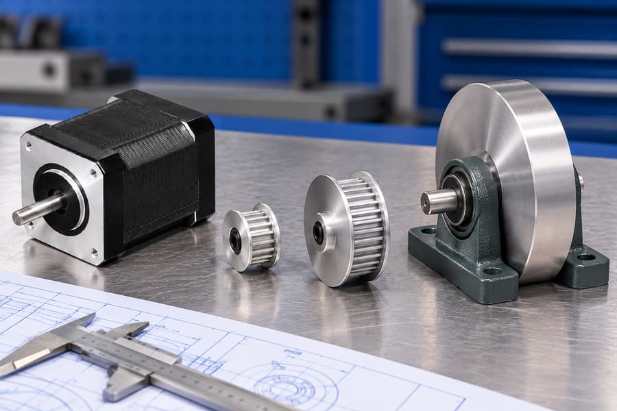
Identify Every Rotating Component
Start with the motor rotor, then identify couplings, hubs, pulleys, gears, screws, shafts, and the driven load. Each component contributes according to its actual rotational axis.
Rotor inertia remains present even without an external payload. Include coupling inertia and motor-side transmission components rather than treating the driven load as the entire system.
Use supplier dimensions or verified inertia data wherever possible. A component’s mass alone cannot establish its rotational inertia without considering geometry and its axis of rotation.
Table 1. Inertia Components and Motor-Shaft Referencing
| Component | Information Needed | Motor-Shaft Treatment |
| Motor rotor | Rotor inertia | Add directly |
| Coupling and input hub | Polar inertia | Add directly |
| Motor-side pulley or gear | Inertia about shaft | Add directly |
| Output gear, shaft, or pulley | Inertia and speed ratio | Reflect through ratio squared |
| Driven rotary load | Inertia about load axis | Direct or reflected |
| Translating mass | Mass and motion geometry | Convert to equivalent rotary inertia |
Treat catalog inertia values as measurements about specified shafts, not interchangeable numbers. A gearbox’s input-referred inertia should not be reflected again when combined with rotor data.
Convert Linear and Geared Loads
For a translating belt load without slip, equivalent pulley-shaft inertia is mass multiplied by effective pulley radius squared. Reflect that result again if gearing separates pulley and motor.
For an ideal screw drive, translating mass contributes equivalent screw-shaft inertia of mass × (lead / (2 × pi))². Rotating screw inertia is separate.
Define gear ratio i = motor speed / output speed. With an ideal fixed-ratio transmission, load inertia referred to the motor becomes Jref = Jload / i².
Acceleration transforms in the opposite direction: alphaMotor = i × alphaOutput. A higher reduction ratio lowers reflected output inertia but demands proportionally greater motor angular acceleration.
For multiple transmission stages, refer each inertia through the speed ratio between its own shaft and the motor. Do not apply the final ratio to every component.
Total motor-referred inertia is the sum of rotor inertia, coupling inertia, correctly referenced transmission inertia, and reflected load inertia. Avoid counting an output assembly both separately and inside a supplied aggregate value.
Check the Calculation Boundary
Record whether published gearbox inertia already includes input gears or attached couplings. Clear component boundaries prevent double counting and make later torque calculations traceable.
Use consistent units, normally kilogram-square-meters for rotational inertia and radians per second squared for acceleration. Label every reflected value with its reference shaft.
What Motor Torque Is Needed During Load Acceleration and Braking?
Calculate Direct-Drive Acceleration Torque
For direct drive, use Trequired = Jtotal × alpha + Texternal + Tfriction, with external and friction demands signed consistently for the selected positive rotation direction.
Here, alpha is motor angular acceleration, and Jtotal includes every motor-shaft inertia. An assisting external force may reduce required torque; an opposing force increases it.
During deceleration, inertial torque changes sign. Gravity, process forces, and friction must still be evaluated according to direction rather than assumed always to increase motor demand.
For each motion segment, evaluate peak positive and negative torque at its actual speed. An acceptable average torque does not establish sufficient acceleration capability.
Separate Ideal Gearing from Real Losses
For lossless gearing, motor-side inertias use motor acceleration, while output-side inertia is reflected by i². Output external torque becomes motor-side torque divided by i.
That ideal relationship does not describe bearing friction, gearbox drag, or backdriving losses. Actual loss torque depends on operating conditions and mechanical power-flow direction.
Do not multiply the entire reflected inertia by a single efficiency factor. Instead, model transmission losses separately, distinguishing motoring from braking or load-driven operation.
Check Signed Torque Throughout the Cycle
Accelerating a rotary axis requires torque proportional to total motor-referred inertia and angular acceleration. External forces and friction must be added with consistent signs.
Choose a positive shaft direction before calculating. A resisting process load increases motor demand in that direction, while an assisting load reduces it.
When the axis decelerates, angular acceleration reverses sign. The motor may need negative torque even while shaft speed remains positive, depending on external forces.
Gravity creates a particularly important distinction. Depending on travel direction, it can oppose lifting, assist lowering, or drive the mechanism independently of commanded motion.
In a lowering axis, net motor torque may switch direction within one move. The controller and drive must handle braking demand without losing synchronization.
Calculate acceleration, constant-speed travel, deceleration, reversal, and dwell separately. Examine both torque magnitude and sign rather than choosing one unsigned peak value.
With gearing, output-side inertial and external terms must be reflected to the motor shaft, while rotor-side terms remain at motor speed and acceleration.
An increased reduction ratio lowers reflected output inertia but raises motor speed and acceleration for the same output motion. The net benefit must be calculated.
Account for mechanical losses in the actual power-flow direction. Friction and gearbox efficiency during driven motion may differ from backdriving or braking behavior.
How Should Torque-Speed Capability Be Matched to High Inertia?
Compare Required and Available Torque at Every Speed
Holding torque describes a stationary, energized motor under specified conditions. It does not show the torque available during rapid rotation or acceleration.
Use a torque-speed curve relevant to the selected motor, drive, supply voltage, winding connection, and current setting. Similar motor dimensions cannot establish equivalent performance.
Published curves may reflect fixture conditions or temperatures unlike those inside the machine. Examine their measurement basis before choosing a working margin.
Stepper torque generally decreases as speed rises because phase current becomes harder to establish within each electrical cycle. Driver and winding characteristics shape this decline.
Plot required signed torque against motor speed throughout the complete ramp. Check positive and negative torque demands, including conditions immediately before stopping or reversing.
Leave application-appropriate margin between required torque and usable dynamic capability. An operating point touching a published pull-out curve is not a dependable design target.
Acceleration can be most demanding near a transition rather than at maximum speed. Evaluate the complete trajectory instead of checking only its start and endpoint.
A gearbox can improve output torque capability at some operating points, yet higher motor rpm may place the stepper in a weaker torque-speed region.
There is no universal permissible load-to-rotor inertia ratio. Demonstrated performance depends on the combined mechanical system, torque margin, drive, ramp, and disturbance environment.
How Do Driver Settings Affect High-Inertia Performance?
Verify Electrical Compatibility
Confirm the actual driver supply voltage and permissible operating range, not merely the nominal motor voltage. Supply voltage influences high-speed current regulation and torque.
Set phase current using the driver’s documented convention. A displayed peak current and an RMS current are not interchangeable without considering the specified waveform.
Check whether the current setting refers to phase peak, phase RMS, or another manufacturer-defined quantity. Measure or verify it using an appropriate method.
Current reduction during idle periods can lower heating, but also changes available static torque. Assess its effect on any loaded stop or restart.
Check Pulse Generation and Thermal Duty
Controller pulse capacity must accommodate motor full steps per revolution, selected microstep subdivision, maximum motor rpm, and acceleration pulse timing without missed commands.
For illustration, pulse frequency equals full steps per revolution multiplied by microsteps per full step and motor revolutions per second, assuming step-and-direction control.
Pulse bandwidth also involves timing quality. Check the controller’s changing pulse intervals and the driver’s minimum accepted pulse high and low durations.
Microstepping can improve commanded smoothness and reduce some excitation, but does not guarantee equivalent incremental accuracy or increase the motor’s fundamental torque capability.
Consider motor heating during acceleration, cruising, and energized holding, alongside driver temperature and cooling. Repeated cycles can differ thermally from short demonstrations.
How Should Motion Profiles Reduce Missed Steps and Resonance?
Shape Acceleration for the Real Mechanism
Abrupt acceleration changes can excite flexible couplings, belts, gear trains, and supporting structures. Trapezoidal ramps are straightforward but may introduce sharp torque transitions.
Jerk-limited profiles smooth acceleration changes and sometimes reduce vibration. They are not automatic cures for resonance, insufficient torque, or structural compliance.
Reducing acceleration lowers inertial torque demand, but can extend cycle time or prevent the axis from reaching its intended cruising speed within available travel.
Verify Resonance and Settling
Sweep relevant speeds in both directions while monitoring vibration, noise, position, and settling. A problematic speed band may appear during transitions or steady motion.
Test reversals and loaded stops because reflected inertia, backlash, friction changes, and compliance affect settling differently from constant-direction travel and opposite-direction target approaches.
Adjust ramps, drive settings, or mechanical damping according to measured behavior. Validate each change across the full duty cycle, not one favorable speed.
How Should the Selected Motor Be Tested and Approved?
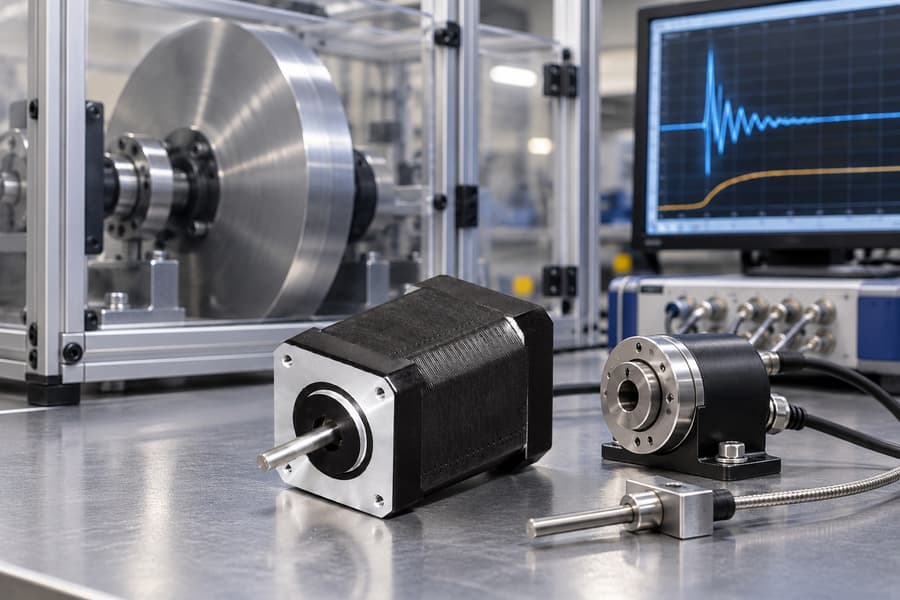
Validate Performance Under Representative Loads
A calculated motor selection must be verified on the actual mechanism or a representative test assembly. Inertia calculations cannot fully predict compliance, friction variation, or mechanical disturbances.
Build the test around the approved motion cycle, including acceleration, constant-speed movement, deceleration, reversals, and holding periods. Use the intended controller and driver configuration.
Test the normal operating load and the worst permitted load condition. Include maximum payload inertia, unfavorable external forces, and the expected range of transmission resistance.
For gravity-influenced axes, the highest resisting load may occur during upward travel, while downward motion introduces different braking and uncontrolled-motion risks.
Record actual shaft speed, commanded acceleration, driver settings, and supply conditions. Compare these measurements with the assumptions used in the original sizing calculations.
Where reduction gearing is installed, verify the selected geared stepper motor against actual output motion, transmission losses, and available torque at the corresponding motor speed.
Measure Positioning, Repeatability, and Settling
Positioning performance should be measured at the working load rather than inferred from commanded step counts. Lost motion, elastic deformation, and missed steps can affect actual displacement.
Use a suitable external encoder, displacement sensor, or calibrated measurement system at the load. Select measurement resolution and uncertainty appropriate to the application’s acceptance requirements.
Measure absolute positioning error against the commanded target and repeatability across repeated movements.
Absolute positioning error and repeatability evaluate separate aspects of motion performance, so each must be measured and assessed independently against its specified acceptance criteria.
Settling time begins when the commanded movement reaches its intended endpoint and ends when measured load motion remains within the defined position tolerance band.
Repeat measurements after forward moves, reverse moves, and direction changes. Mechanical backlash and compliance can produce different final positions depending on the approach direction.
Perform cold-start tests and repeat the same sequences after thermal stabilization. Changes in winding temperature, lubrication behavior, and mechanical dimensions can influence operating performance.
Include repeated start-stop cycles and restart behavior where required. A motor that completes isolated movements may behave differently after continuous operation or accumulated heating.
Determine Whether Position Feedback Is Necessary
Open-loop operation is appropriate only when the mechanical system reliably follows commanded movement within the required tolerances across all specified operating conditions.
A motor-mounted encoder can detect rotor position errors and support corrective control. However, it cannot directly measure backlash, belt compliance, or displacement errors downstream.
Load-side feedback measures the actual controlled position and can reveal transmission-related errors. Its usefulness depends on sensor accuracy, controller design, and mechanical response.
Feedback does not create additional motor torque. If acceleration demand exceeds available dynamic capability, closed-loop correction cannot guarantee completion of the commanded trajectory.
Specify how the controller responds to excessive following error, overload, or stalled motion. Recovery procedures must account for machine safety and position-reference integrity.
Verify Holding and Fault Conditions Separately
A gravity-loaded axis requires explicit analysis of stationary holding and unexpected power loss. Motor holding torque is not automatically available when electrical power disappears.
If the application requires mechanical restraint, specify a suitably rated holding brake or another approved protective mechanism. Verify its compatibility with the complete drive assembly.
A holding brake is not automatically suitable for routine dynamic stopping. Dynamic braking requires separate manufacturer approval and ratings for the relevant stopping energy and duty.
Test the intended brake engagement sequence, release timing, and power-loss response under permitted loads. Prevent uncontrolled movement during transitions between electrical torque and mechanical restraint.
Establish Measurable Acceptance Criteria
Acceptance limits must come from machine requirements and approved component documentation. Arbitrary universal tolerances cannot establish whether a high-inertia stepper system is suitable.
Table 2. High-Inertia Motor Selection and Acceptance Tests
| Test Item | Required Evidence | Acceptance Basis |
| Acceleration and deceleration | Measured motion profile and following error | Approved cycle and position limits |
| Worst-case load | Load record and completed motion tests | Maximum specified operating load |
| Dynamic torque margin | Torque-speed comparison at actual driver settings | Approved operating margin |
| Positioning and repeatability | Load-side position measurements | Application-defined tolerances |
| Resonance and settling | Vibration and settling measurements | Required motion stability |
| Thermal performance | Stabilized motor and driver temperatures | Documented component limits |
| Reversal and restart | Recorded responses under representative conditions | Approved functional requirements |
| Power-loss holding | Brake and load-retention test records | Machine safety requirements |
Use consistent measurement methods across test repetitions. Record instrumentation, calibration status, load conditions, operating temperature, and any deviations from the approved test procedure.
Where results approach acceptance boundaries, investigate measurement uncertainty and operating variation. A single successful cycle should not establish reliability across the complete operating envelope.
Before approval, obtain supplier-reviewed records identifying motor winding configuration, driver model and current convention, supply voltage, gearing, acceleration ramps, and thermal duty.
The final acceptance record should connect those approved settings with measured load position, repeatability, settling, temperature, fault behavior, and documented test results.