
A geared stepper layout affects more than the gearbox footprint: shaft direction, wiring, mounting access, and maintenance paths all compete for limited machine space.
Compare the complete installed envelope separately from the space needed to install, inspect, remove, or service the assembly; a compact outline can still create an awkward machine layout.
How Do Coaxial, Offset, and Right-Angle Geared Stepper Configurations Differ?
Coaxial inline means the motor shaft axis and gearbox output shaft axis lie on the same centerline. The gearbox may extend the assembly axially, so length along that axis often becomes the first packaging constraint.
Parallel-axis offset means the input and output shafts run parallel but occupy different centerlines. The offset can move the output toward a neighboring component, reducing one dimension while increasing another; check housing and shaft positions.
Right-angle describes input and output axes arranged at 90 degrees. It redirects motion around a corner, but the term describes shaft geometry rather than a specific gear mechanism or guaranteed package size.
A right-angle gearbox is not necessarily a worm gearbox. Bevel, worm, and other arrangements may provide perpendicular axes, depending on the design; likewise, do not assume a worm gearbox will hold a load without power.
Choose the geometry from the required shaft direction first, then compare real drawings. A layout label alone cannot establish overall dimensions, efficiency, allowable loads, backlash, or whether a particular configuration is offered.
| Layout | Shaft relationship | Main packaging question |
| Coaxial inline | Input and output share one axis | Is there enough axial room for the motor, gearbox, coupling, and shaft access? |
| Parallel-axis offset | Input and output axes are parallel but displaced | Does the offset clear adjacent parts without widening the assembly envelope? |
| Right-angle | Input and output axes are perpendicular | Is the turned output direction useful after allowing for housing, wiring, and service access? |
For dimensions and configuration details, review the geared stepper motor information, then verify the proposed assembly’s drawing and specifications instead of inferring availability or performance from its layout name.
How Do Installed and Service Envelopes Differ?
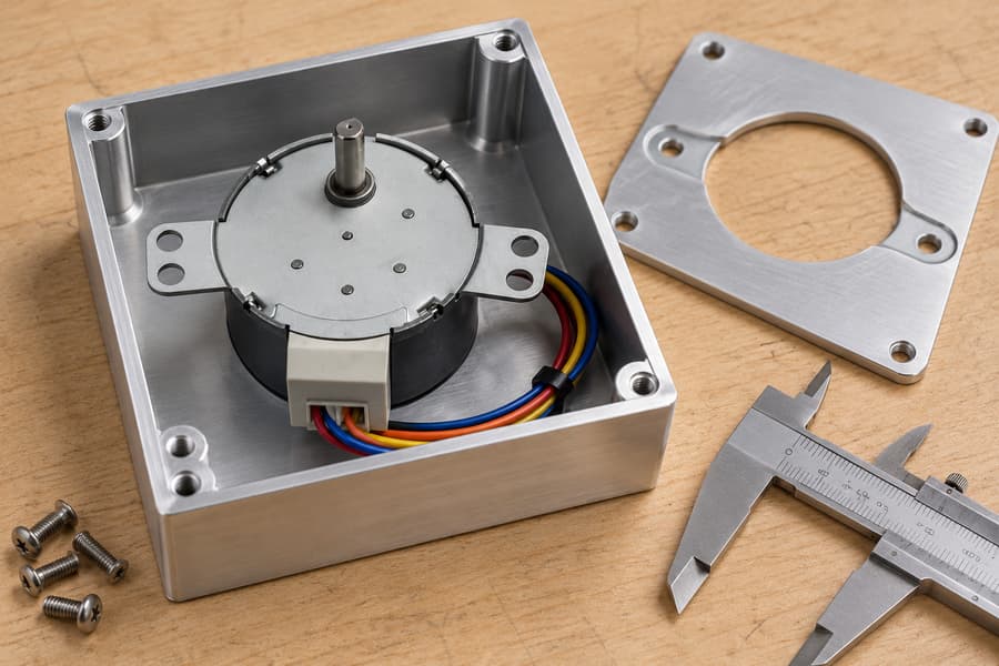
The installed envelope is the space occupied by the assembled unit in its normal operating position. Include the motor body, gearbox housing, projecting output shaft, coupling, mounting plate, fasteners, and any permanently attached accessories.
Do not measure only the gearbox outline. A coupling may extend the axial length, a mounting flange may add width, and a shaft or fastener may project beyond the housing’s nominal dimensions.
Electrical connections also consume real space. Allow for the connector body, plug removal direction, cable exit, minimum permitted cable-bend radius, strain relief, and the route needed to keep wiring clear of moving or hot components.
Installation orientation changes the envelope. A connector that clears a side panel in one position may face a frame after rotation; a shaft accessible from above may be blocked below a shelf.
The service envelope is the additional access space and movement path needed to inspect, adjust, disconnect, remove, or replace components. It can include tool swing, fastener access, unplugging, and withdrawal.
Keep service space separate from permanent occupied volume in layout drawings. A removable cover may need temporary clearance while it is lifted away, but that removal space is not necessarily occupied during normal operation.
Service access remains important even when temporary. If a cover must slide sideways before lifting, or the gearbox must withdraw along its shaft axis, nearby guards and frames must leave that path clear.
Plan access around the task. Routine inspection may need visibility and a hand or tool opening; replacing a coupling, releasing a keyed shaft, or removing the assembly may need a longer path.
A useful drawing therefore shows at least two boundaries: the permanent installed envelope and the service envelope. Add cable-bend and connector-removal requirements explicitly, because neither is reliably represented by the bare motor or gearbox dimensions.
Before fixing the bay size, confirm installation direction, mounting face, shaft projection, coupling dimensions, connector orientation, cable specification, and removal sequence. Mark undecided clearances as design allowances, not verified dimensions.
Parallel offset is not right-angle geometry: both shaft axes remain parallel, while right-angle layouts turn the output axis by 90 degrees. This changes the connection to the driven mechanism.
Compare dimensions from the same reference points and in the intended mounting orientation. Overall length, width, and height alone can conceal shaft-center locations, connector protrusions, or a coupling that crosses the nominal housing boundary.
Also consider the sequence for removing adjacent parts. A gearbox may fit yet be impossible to withdraw until a belt, guard, or bracket is removed; document dependencies before releasing the layout.
Which Layout Fits a Hypothetical Machine Bay?
Assume a machine bay provides 220 × 180 × 160 mm of clear space, measured length × width × height. These are illustrative design assumptions, not Leili product dimensions or specifications.
For this example, each installed envelope includes the motor, gearbox, output shaft, coupling, mounting hardware, and connector body. Cable-bend allowance and service access are listed separately because they depend on routing and maintenance procedures.
A coaxial inline assembly may fit the bay’s 220 mm length on paper, yet a connector exiting along that axis can require additional bend space. The fixed assembly length is not the whole installed requirement.
A right-angle unit may shorten the length while placing its connector or housing across the available width.
A parallel-axis offset arrangement may use the middle ground, but its displaced shaft centerline still needs clearance around the driven mechanism.
| Hypothetical layout | Fixed installed envelope (L × W × H) | Cable-bend allowance | Resulting envelope check against 220 × 180 × 160 mm bay | Separate service-path requirement |
| Coaxial inline | 205 × 95 × 110 mm | +35 mm along length | 240 mm length exceeds the bay | 60 mm axial withdrawal path after uncoupling |
| Parallel-axis offset | 175 × 125 × 120 mm | +35 mm along width | 175 × 160 × 120 mm fits nominally | 45 mm side access for fasteners; 80 mm withdrawal path |
| Right-angle | 145 × 150 × 115 mm | +45 mm along width | 195 mm width exceeds the bay | 70 mm gearbox withdrawal path; connector unplug access |
Every figure in this table is hypothetical. The resulting envelope check adds the stated cable allowance only along its assumed direction; it does not convert maintenance clearance into permanent occupied volume.
The comparison shows why one-axis length is insufficient. The inline layout passes the length check before cable routing but fails after its bend allowance; the right-angle layout fails the width check.
The offset example passes the assumed installed-envelope check, but it is not automatically the best choice. Its output shaft position, coupling alignment, and separate withdrawal path must also work within the real machine.
Service-path dimensions are independent of the permanent envelope. A removal path may extend through an access panel or into a temporarily cleared aisle, provided the maintenance procedure genuinely permits that space to be available.
Output Bearing Loads and Lever-Arm Effects
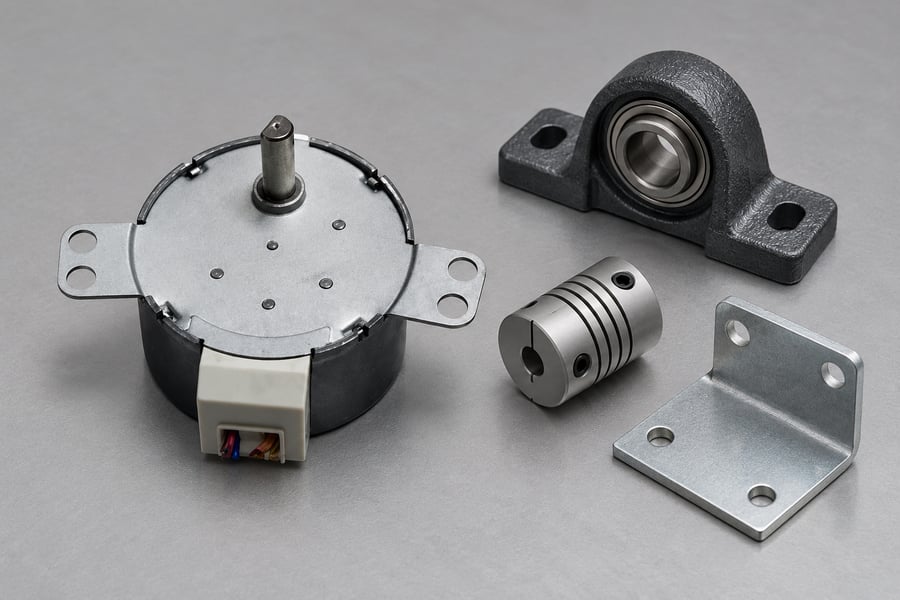
Packaging changes can alter how the driven load acts on the gearbox output. A pulley, belt, sprocket, or coupling may apply radial or axial force, depending on the transmission arrangement.
An overhung load acts at a distance from the supporting bearing. Its bending effect increases with both force and offset distance, so moving a driven component outward can raise bearing demand without changing its mass.
Measure the perpendicular distance from the selected bearing reference to the applied force’s line of action, then multiply that distance by the force to determine the bending moment.
Real designs may also require belt pretension, acceleration forces, shock loads, and load direction to be considered.
Do not assume the gearbox output shaft can carry the driven mechanism directly. Check the specified radial and axial load limits, the distance at which each limit applies, and any restrictions on simultaneous loading.
A right-angle arrangement may redirect the drive but place the load farther from a bearing. An inline arrangement can also create excessive overhang when a long coupling or pulley is added.
Compare candidate layouts using the actual shaft extension, coupling geometry, driven-component center of load, and bearing support. If the external load exceeds the gearbox’s permitted capacity, a separate support bearing may be necessary.
Design-Specific Efficiency and Gearbox Ratings
Gearbox efficiency depends on the particular transmission design and operating conditions, not simply whether the shafts are inline, offset, or perpendicular. Gear geometry, stage count, ratio, speed, load, and temperature can all affect losses.
Avoid treating all right-angle gearboxes as less efficient or all worm arrangements as self-locking.
Self-locking behavior, where relevant, depends on the specific design and operating conditions; it should not be used as an assumed safety or holding function.
Check rated output torque alongside input speed, duty cycle, permissible peak loads, and thermal limits. A nominal torque figure alone may not describe continuous operation, repeated acceleration, or an application with frequent starts and stops.
Check that the gearbox’s allowable torque is compatible with the stepper motor’s torque capability at the required operating speed.
Holding torque does not represent usable dynamic torque throughout the operating range; check the motor data at the required operating point.
Use Leili’s stepper motor information as a starting point for motor-side requirements, then compare the actual candidate’s documented ratings rather than assuming every layout has the same performance.
Mounting Orientation and Lubrication
Mounting orientation can affect lubrication distribution, heat dissipation, and access to mounting hardware. Confirm the gearbox manufacturer’s permitted orientations rather than assuming every position is acceptable.
A gearbox mounted vertically may place the motor, output shaft, or lubricant reservoir differently from a horizontal installation. Verify orientation-specific restrictions, lubricant requirements, and any associated rating changes before fixing the machine frame.
Lubrication requirements depend on the gearbox design and its specified operating conditions. Check the approved lubricant type, filling procedure, maintenance interval, and any restrictions affecting continuous operation or temperature.
The physical mounting arrangement also influences serviceability. A bracket that improves stiffness may obstruct a fill plug, inspection point, or fastener, making routine maintenance difficult without disturbing adjacent equipment.
Reversal Duty, Backlash, Reflected Inertia, Speed and Available Torque
Frequent reversals impose different demands from steady unidirectional rotation. Each acceleration, deceleration, and direction change affects motor torque demand, gearbox loading, positioning behavior, and potentially the mechanism’s service life.
Backlash describes lost motion when the output changes direction before the opposite tooth flanks or transmission elements engage. Its effect becomes particularly noticeable when an axis repeatedly approaches a target from alternating directions.
The relationship between gearbox backlash and final positioning error depends on the transmission ratio and measurement reference. Assess output-side motion directly where practical instead of converting nominal gearbox figures into an assumed machine accuracy.
A gearbox with lower backlash is not automatically the best choice for every application. Consider the required positioning tolerance, reversal frequency, loading direction, compliance elsewhere in the drive train, and repeatability under actual operating conditions.
Reflected inertia also affects layout selection. For an ideal reduction ratio i, the load inertia reflected to the motor shaft is Jload/i2, excluding gearbox inertia and transmission losses.
This relationship helps estimate motor-side acceleration demand, but it does not replace the manufacturer’s ratings. Gearbox input inertia, output-side inertia, friction, compliance, and dynamic load behavior still influence the complete system.
Higher reduction ratios can reduce reflected load inertia while increasing motor speed for a given output speed. Check whether the motor can supply sufficient torque at that operating speed, including acceleration and reversal peaks.
Available stepper motor torque varies with operating speed and drive conditions. Compare the required torque profile against documented motor performance, allowing for the selected gearbox’s losses rather than relying on standstill holding torque.
Consider the entire motion cycle, including dwell periods and repeated starts. A gearbox that handles an occasional peak may still experience unacceptable heating when the same event occurs continuously throughout production.
Mechanical resonance, coupling compliance, and frame flexibility can also affect positioning during reversals. Evaluate the assembled axis rather than attributing every oscillation or settling problem to the gearbox alone.
How Should the Selected Layout Be Verified?
Begin with supplier drawings for the exact proposed motor and gearbox configuration. Confirm housing dimensions, shaft centerlines, output projection, mounting interfaces, permitted orientation, and documented mechanical and thermal ratings.
Overlay those dimensions onto the machine assembly in its intended installation direction. Include the coupling, driven components, fasteners, connector bodies, guards, and surrounding structure rather than checking the motor and gearbox independently.
Cable clearance must be maintained during normal operation, not merely during maintenance. Verify the actual cable exit direction, specified bend radius, connector engagement, strain relief, and routing throughout the mechanism’s complete movement.
Check the cable path at travel limits and during acceleration, where movement or vibration may bring wiring closer to adjacent parts. A route that fits in the stationary drawing can still interfere during operation.
Evaluate maintenance access separately from operational clearances. Determine whether technicians can reach fasteners with the specified tools, disconnect electrical connections, release the coupling, and withdraw the assembly along its required removal path.
If removal requires temporarily taking off a guard or adjacent bracket, document that sequence. Confirm that the procedure is practical and that the required temporary clearance can actually be provided at the installation site.
Once the geometry is approved, test the assembled axis with its representative load. Exercise the intended speeds, acceleration profiles, reversal frequency, dwell periods, and operating cycle rather than relying solely on unloaded rotation.
Measure motor and gearbox temperatures over a representative duty period, comparing results with the applicable documented limits. Investigate unexpected heating, noise, vibration, or changes in motion before accepting the configuration.
Verify positioning and repeatability using the machine’s actual measurement reference. Test approaches from both directions, representative load conditions, and relevant operating temperatures, recording observed errors against application-specific acceptance criteria.
Where positioning degrades after repeated reversals, investigate backlash, coupling movement, structural compliance, and thermal effects separately. Record the test method, instrument resolution, operating conditions, and any adjustments made before repeating acceptance measurements.
The final approval record should identify the selected motor and gearbox, the approved drawing and revision, and the installation orientation.
Attach measured clearance results, cable-routing verification, service-access evidence, and motion, temperature, and positioning test results to establish the accepted configuration.