
Choosing between a single-stage and multi-stage geared stepper requires more than comparing reduction ratios. Gear layout affects transmission losses, package dimensions, backlash, and the torque available under real operating conditions.
Useful comparisons hold total ratio and output duty constant, then assess each gearbox at its actual speed, load, temperature, and lubrication condition.
What Defines Single-Stage and Multi-Stage Gearboxes?
A gear stage is one meshing or transmitting reduction set between an input and output member. A single-stage gearbox achieves reduction through one gear set, whereas a multi-stage design transmits motion through successive reduction sets.
Determine an individual stage’s ratio by dividing its rotational input speed by its rotational output speed. In a compound gearbox, the overall reduction ratio is the product of its individual stage ratios.
Written plainly, total ratio = stage ratio 1 × stage ratio 2 × … × stage ratio n. The ratios multiply; they are not added.
To illustrate, a hypothetical 12:1 total reduction could use one 12:1 stage, two stages of 3:1 and 4:1, or three stages of 2:1, 2:1, and 3:1.
These ratios are arithmetic examples only, not claims that every arrangement is practical within a particular gearbox type, size, or operating envelope.
The same total ratio can provide the same nominal output speed from a given input speed, but internal gear speeds, tooth loads, bearing loads, and packaging may differ.
Those differences influence efficiency, temperature, wear, and the available housing envelope, so stage count should be considered alongside the actual transmission architecture.
When evaluating a geared stepper, start with required output torque, speed, movement profile, and holding condition. Then compare gearbox architectures capable of meeting those requirements.
Leili Motor’s geared stepper motor range is a useful starting point for an initial technical review of integrated motor-and-gearbox configurations.
How Do Gearbox Losses Change with Configuration?
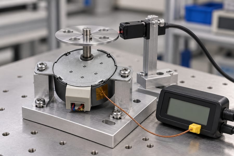
Gearbox losses arise from gear-mesh friction, bearing friction, seal drag, and lubricant churning. Their relative contributions depend on gear type, geometry, material, lubrication, temperature, speed, load, and assembly details.
A stage adds interfaces and rotating components, but that alone does not establish a universal efficiency ranking. A well-designed multi-stage arrangement may use favorable ratios at each stage.
Conversely, a single high-ratio stage may require geometry that produces different contact, bearing, or lubrication losses. Compare complete designs rather than inferring performance from stage count alone.
For a first-order estimate, multiply the efficiencies of individual stages, provided each value applies at the relevant operating point. With two stages, overall efficiency = stage 1 efficiency × stage 2 efficiency.
For three stages, overall efficiency = stage 1 efficiency × stage 2 efficiency × stage 3 efficiency. This product estimates gearbox transmission efficiency, not motor-drive system efficiency.
The following numbers are deliberately hypothetical arithmetic examples, not Leili Motor product data, measured results, or general efficiency expectations. All arrangements assume the same total ratio and output duty.
Specifically, the example assumes a 12:1 ratio, 300 rpm input, 25 rpm output, and 0.5 N·m output torque. Each stage efficiency is stipulated solely for illustration.
| Hypothetical arrangement | Assumed stage efficiencies | Overall gearbox efficiency |
| One 12:1 stage | 92% | 92.00% |
| 3:1 × 4:1 stages | 96% × 96% | 92.16% |
| 2:1 × 2:1 × 3:1 stages | 97% × 97% × 97% | 91.27% |
The table demonstrates the multiplication method, not a design rule. Actual per-stage efficiencies require measurements or applicable engineering data; the assumed values cannot predict the best layout.
Keep gearbox shaft efficiency separate from electrical-input system efficiency. Gearbox shaft efficiency = mechanical output power at the gearbox shaft ÷ mechanical input power at the gearbox input shaft.
Electrical-input system efficiency = mechanical output power at the gearbox shaft ÷ electrical power drawn by the motor-drive system. This broader figure includes motor and drive losses.
Mechanical shaft power = torque × angular speed. At zero output speed, output mechanical power is zero even if the gearbox resists a load, so the power ratio is not a useful motion-efficiency rating.
Evaluate holding torque, backdriving behavior, and power-off load retention separately. Static holding concerns resisting movement, not conversion of input power into useful rotating output.
Fixed losses can represent a larger share of transmitted power when the gearbox carries a light load. Mesh and bearing losses may not fall proportionally with output load.
Consequently, the percentage of input power lost may rise at low load even when absolute losses change little. This is a fractional effect, not necessarily a sudden deterioration in hardware.
Churning losses often increase with rotational speed because moving parts agitate lubricant more vigorously. The exact trend depends on lubricant viscosity, fill level or grease distribution, clearances, and gearbox design.
Do not assume one universal speed-loss curve. Evaluate representative operating points, because lubrication choices and internal geometry can change how losses develop as speed rises.
Evaluate each candidate over the full application duty cycle, covering representative operating conditions rather than relying on a single rated point. Include starts, stops, sustained running, load changes, and thermal stabilization where relevant.
Efficiency and temperature can differ between transient and steady operation, so record test conditions with each result. This makes comparisons traceable and prevents unlike measurements from being treated as equivalent.
How Do Stage Count and Packaging Affect Size?
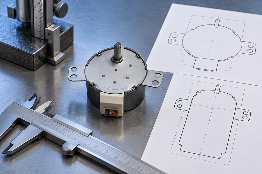
Stage count changes how reduction is distributed through the gearbox, but it does not determine the envelope alone. Gear type, stage ratios, center distance, bearings, and housing design all matter.
A single high-ratio stage may need a larger gear diameter or greater center distance to achieve the reduction within acceptable tooth geometry and loading. This can increase radial dimensions.
A multi-stage layout can divide the total ratio across smaller gear sets, potentially reducing the largest gear diameter. The trade-off is added shafts, bearings, meshes, and spacing that may extend axial length.
This is not a universal size advantage. A multi-stage arrangement may fit a narrow diameter limit but exceed available length; another design may fit a wider, shallower housing.
Ask how the ratio is divided across stages and which stage carries the highest speed and torque. These details influence tooth loading, bearing selection, lubricant behavior, and heat.
Ask for the full envelope drawing, not only gearbox diameter or face dimensions. Check overall length, mounting features, shaft projection, connector access, and installation or removal space.
Center distance matters when the gearbox connects to belts, pulleys, couplings, or driven mechanisms. A gearbox may fit the motor footprint yet create awkward transmission geometry or interfere with nearby parts.
Output bearing support matters when the driven load applies radial or axial forces. Confirm permitted bearing loads and the conditions behind each rating, including load direction and speed.
An overhung pulley or coupling applies force away from the bearing support. Greater offset can raise bending moment and bearing stress, so check load position alongside output torque.
Housing stiffness, shaft support, lubrication, and sealing also affect packaging. Extra stages may need additional bearing locations, while a large single-stage gear may require more radial clearance.
Check whether the gearbox can be mounted in the intended orientation without changing lubrication performance. A compact drawing is insufficient if oil level or grease distribution depends on orientation.
Service access is part of the usable size. Leave room for mounting screws, cable routing, inspection, lubricant service where applicable, and removal without dismantling unrelated equipment.
Compare the complete installed envelope, including motor, gearbox, connectors, coupling, and maintenance clearance. Nominal gearbox dimensions alone cannot establish whether the assembly fits and remains serviceable.
How Should Buyers Compare Equivalent Configurations?
Start with one common operating requirement for every candidate. Specify total reduction ratio, output speed and torque, motion profile, load inertia, duty cycle, ambient conditions, and expected service life.
Do not compare one gearbox at efficient mid-load with another at low speed or near its load limit. Use equivalent application operating points and comparable thermal conditions.
For intermittent movement, describe acceleration, travel time, dwell, stopping frequency, and holding periods. For continuous operation, specify sustained speed and torque because heat and lubrication behavior can differ.
Ask whether rated output torque applies continuously, intermittently, or under a defined thermal condition. Also check whether speed, torque, and service-life ratings assume particular mounting and lubrication conditions.
Backlash comparisons need a common reference shaft. Stage angle values cannot simply be added when they describe different shafts, because each angle represents a different output displacement.
For an ideal ratio model, refer each stage’s angular contribution to the final output by dividing by the product of subsequent stage ratios. Combine contributions only after conversion to that same shaft.
Actual lost motion may also reflect tooth clearance, bearing clearance, shaft compliance, housing deflection, and measurement method. Request the supplier’s definition and test setup before comparing arcminutes.
The initial purchase price represents only part of the total ownership cost. Consider assembly complexity, lubrication requirements, expected wear, replacement access, downtime consequences, and the cost of maintaining output performance.
Additional stages introduce more components and interfaces, but component count alone does not establish reliability. Tooth loading, bearings, materials, lubrication, manufacturing quality, and environment can outweigh stage count.
Likewise, a single-stage design is not automatically cheaper or more robust. A large gear, specialized housing, or demanding tooth geometry may offset savings from fewer components.
Ask which failure modes matter: tooth wear, bearing fatigue, lubricant degradation, seal wear, overheating, or excessive lost motion. Then request evidence supporting the expected service interval under the proposed duty.
Request identical duty-cycle assumptions for life estimates, including starts per hour, reversals, shock loads, and daily operating time. Otherwise, quoted service lives may not be comparable.
Motor compatibility matters too. A gearbox changes required motor speed and torque, while available motor torque depends on speed and drive conditions.
Review motor and transmission together against the intended load profile. Leili Motor’s stepper motor range can help frame motor-side requirements alongside gearbox selection.
Before narrowing the shortlist, request comparable drawings, ratings, efficiency conditions, backlash definitions, allowable output loads, lubrication details, and service assumptions. Consistent evidence makes trade-offs easier to judge.
How Should Performance Be Validated?
A meaningful comparison requires both gearbox configurations to operate under equivalent output requirements. Define the total reduction ratio, output torque, speed profile, load, duty cycle, mounting orientation, and ambient conditions before testing.
Use the same application-representative operating points for both candidates. Where exact operating conditions cannot be reproduced, document the differences and avoid treating the resulting measurements as directly equivalent.
Measure Actual Shaft Torque and Speed
Measure mechanical input and output torque and rotational speed at the respective gearbox shafts. Record instrument locations, coupling arrangements, calibration status, and operating conditions for every measurement.
Calculate mechanical shaft power from measured torque and angular speed. When torque is expressed in newton-metres and angular speed in radians per second, the resulting power is expressed in watts.
Gearbox shaft efficiency equals output mechanical shaft power divided by input mechanical shaft power. This isolates gearbox transmission performance from losses occurring in the motor and drive.
Electrical-input system efficiency instead divides gearbox output mechanical power by the electrical power supplied to the motor-drive system. This broader measurement includes electrical, motor, and gearbox losses.
Keep the two efficiency figures separate in the acceptance report. If electrical-input efficiency is required, measure electrical power using a method appropriate to the drive waveform and operating conditions.
Account for Measurement Uncertainty and Operating Temperature
Low-power measurements require particular care because instrument offsets and measurement uncertainty may represent a substantial fraction of the measured power. Report uncertainty alongside calculated efficiency rather than overstating small differences.
At low output torque or speed, determine whether the measurement system can resolve the expected mechanical power accurately. If uncertainty overlaps the difference between candidates, report the comparison as inconclusive.
Run each candidate under the specified representative duty until the agreed temperature-stabilization criterion is met. Record gearbox housing temperature, ambient temperature, load, speed, and elapsed operating time.
Use consistent sensor locations and measurement procedures across candidates. Interpret housing temperature alongside the supplier’s applicable temperature ratings and lubrication requirements, not as a direct measurement of every internal component.
A gearbox that performs acceptably during brief movement may behave differently during sustained operation. Include continuous running, intermittent motion, or dwell periods only where they represent the intended application.
Verify Lost Motion, Bearing Loads, and Noise
Measure reversal lost motion using a defined procedure that applies controlled torque reversals and records corresponding output angular displacement. Keep the reference shaft, loading conditions, fixture arrangement, and measurement method consistent.
If input locking is used, specify how the input is restrained and whether the gearbox is tested unpowered or under another defined condition. Do not mix results obtained using different restraint methods.
Distinguish backlash from elastic deflection, fixture movement, and shaft compliance. Report the measurement method and uncertainty, and refer angular contributions to the same shaft before comparing multi-stage configurations.
Check output bearing loads against the supplier’s documented limits, considering radial and axial forces, load direction, and the actual distance between the applied load and bearing support.
Include noise measurements only when acoustic performance is an application requirement or specified rating. Define the measurement position, operating speed, load, background conditions, and applicable acceptance requirement beforehand.
Establish Comparable Acceptance Criteria
The following table provides a compact acceptance framework. Numerical limits should come from documented supplier ratings and application requirements, not assumed universal tolerances.
| Validation item | Measurement or test condition | Acceptance basis |
| Output performance | Measure shaft torque and speed at equivalent duty points | Required output duty and documented ratings |
| Gearbox efficiency | Calculate from mechanical input and output shaft power | Application-defined requirement, accounting for uncertainty |
| Electrical-input efficiency | Measure electrical input and mechanical gearbox output power | System-level requirement, reported separately |
| Temperature | Record temperatures after agreed stabilization under representative duty | Documented thermal limits and application requirements |
| Reversal lost motion | Apply defined torque reversals and measure output displacement | Specified backlash or lost-motion requirement |
| Output bearing loads | Check actual radial and axial loads, including overhang | Applicable supplier load ratings |
| Static holding | Evaluate resistance to movement under the specified holding condition | Required holding performance and documented limits |
| Noise, if specified | Measure under defined speed, load, and acoustic conditions | Agreed acoustic specification |
Static holding must be assessed separately from rotating efficiency. At zero output speed, mechanical output power is zero, so an input-to-output power ratio does not provide a meaningful motion-efficiency rating.
Do not introduce holding loads, temperatures, speeds, or other test conditions beyond documented ratings. Any additional qualification must be agreed with the supplier and confirmed safe for the selected configuration.
Document the Selected Configuration
Request supplier drawings, stage ratios, rated operating conditions, efficiency definitions, backlash specifications, bearing-load limits, lubrication instructions, and applicable temperature and service-life information.
Record the selected configuration, motor and gearbox identification, test equipment, calibration status, duty profile, environmental conditions, raw measurements, calculated results, uncertainty, and acceptance criteria.
The final acceptance record should identify the test procedure and revision, measured deviations, disposition of unresolved differences, and supplier approval. Retain sufficient evidence for another engineer to reproduce the comparison under the same conditions.