
Single-shaft and double-shaft hybrid steppers share the same operating principle but provide different mechanical interfaces. Before selecting either configuration, OEM engineers should assess accessory needs, available mounting space, and future maintenance accessibility.
A rear shaft can accommodate additional components, but it introduces alignment, loading, and guarding considerations. Comparing complete assemblies helps engineers identify the arrangement that best supports equipment integration.
What Is the Difference Between Single-Shaft and Double-Shaft Hybrid Steppers?
Hybrid steppers achieve controlled movement in discrete angular increments through interacting permanent magnets and toothed magnetic components. Their shaft arrangement determines which mechanical interfaces are accessible for external connections.
The distinction concerns shaft accessibility rather than a fundamental change in stepping operation. Both configurations can be evaluated using the same basic electrical and mechanical selection principles.
Single-Shaft Hybrid Stepper Design
A single-shaft hybrid stepper provides one externally accessible shaft extension, generally used to transmit motion from the motor to the driven mechanism.
This arrangement can simplify rear-end packaging when the application does not require an external encoder, brake, or manually operated adjustment device.
However, a single-shaft configuration does not automatically exclude feedback or braking functions. Supplier-integrated assemblies may incorporate these features through alternative internal arrangements.
Engineers should confirm the actual shaft geometry, mounting surfaces, and available accessory options from the selected motor’s approved technical documentation.
Double-Shaft Hybrid Stepper Design
A double-shaft hybrid stepper provides accessible shaft extensions at opposite ends of the rotor assembly. Their dimensions and mechanical interfaces depend on the specific configuration.
Both extensions rotate together because they belong to the same rotor. They cannot provide independently controlled rotational speeds or positions.
Importantly, adding a second shaft extension does not double the motor’s available torque. Both ends share the electromagnetic torque produced by the motor.
When both ends transmit mechanical loads, their combined torque demand must remain within the motor’s available capability and applicable shaft-interface limits.
The rear extension may accommodate compatible accessories, although its presence alone does not establish that a particular encoder, brake, or coupling will fit.
Table 1: Single-Shaft vs Double-Shaft Hybrid Stepper Integration Comparison
| Integration Factor | Single-Shaft Configuration | Double-Shaft Configuration |
| Drive connection | One accessible shaft extension | Accessible extensions at both ends |
| Rear accessories | May require integrated alternatives | Can support compatible external accessories |
| Installation envelope | May reduce external rear-end requirements | Additional rear clearance may be necessary |
| Mechanical integration | Fewer accessible shaft interfaces | Additional coupling and alignment considerations |
| Rotating-part protection | Guard accessible drive components | Rear extension may require additional guarding |
| Maintenance access | Depends on assembly design | Rear accessory servicing may require access |
Neither arrangement guarantees simpler installation. The advantage depends on the complete mechanical assembly, accessory requirements, and available equipment space.
How Do Rear-Shaft Accessories Affect Motor Integration?
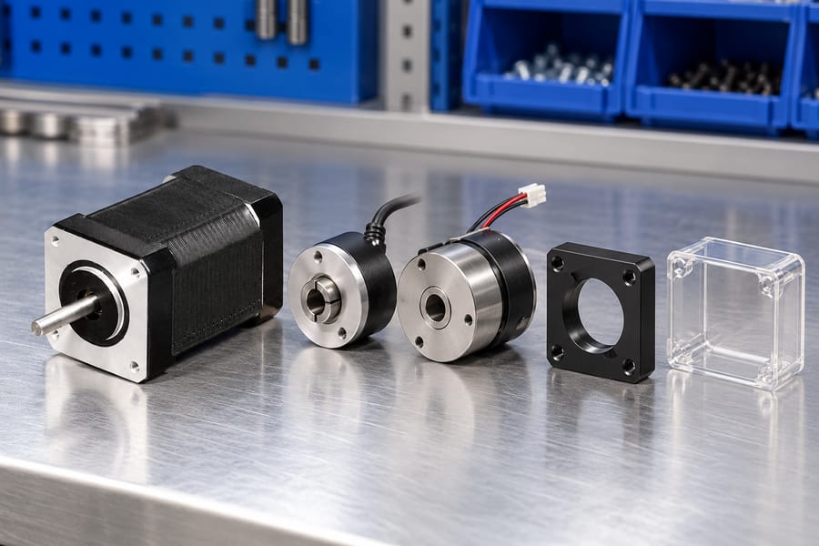
A rear extension can provide a convenient mechanical connection for auxiliary equipment. However, each accessory introduces specific mounting, operational, and maintenance requirements.
Rear-Shaft Encoder Installation
An encoder attached to the rear extension can measure rotor movement and provide position or speed information to a compatible controller.
Mechanical integration requires attention to shaft concentricity, coupling alignment, permissible runout, and encoder mounting stability. Excessive misalignment can compromise measurement reliability or damage components.
Encoder resolution alone does not determine positioning accuracy. Coupling behavior, motor movement, transmission errors, and the feedback control arrangement also influence measured performance.
Engineers should verify the encoder’s mounting interface and cable routing while ensuring sufficient access for inspection, adjustment, and eventual replacement.
Electromagnetic Holding Brake Integration
A rear-mounted electromagnetic brake can help retain shaft position when engaged, provided its holding capacity suits the actual load and transmission arrangement.
A brake intended for stationary load retention should not be assumed capable of stopping a moving mechanism. Permitted engagement speed, stopping energy, and operating frequency require separate verification.
Brake selection must also account for mounting alignment, engagement behavior, release timing, and the consequences of power loss under the intended operating conditions.
Where an application requires a safety-related stopping or holding function, engineers must separately establish whether the selected brake assembly and control architecture satisfy those requirements.
Manual Adjustment and Positioning
A rear extension may accommodate a manual adjustment knob for selected commissioning or maintenance operations, provided the shaft interface and machine design permit it.
Before manual adjustment, isolate electrical power and prevent unexpected movement. Secure gravity-driven loads and stored mechanical energy according to the equipment’s isolation procedure.
During powered operation, exposed rear shafts and attached knobs require suitable guarding to prevent accidental contact with rotating components.
External Accessories vs Integrated Assemblies
External encoders and brakes offer possible configuration flexibility, but they also require appropriate mounting structures, coupling interfaces, electrical connections, and installation clearance.
Supplier-integrated solutions may package accessories differently, potentially reducing external assembly work without necessarily retaining the same accessible rear-shaft arrangement.
For an appropriate starting point, review available hybrid stepper motor configurations and request drawings identifying the actual shaft and accessory interfaces.
Leili Motor configuration options should be assessed through confirmed specifications rather than assumptions about universal accessory compatibility, standardized dimensions, or interchangeable mounting arrangements.
What Shaft Loads and Mechanical Constraints Must Engineers Evaluate?
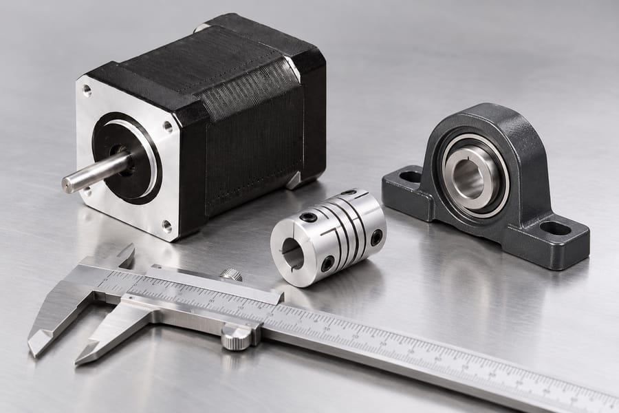
Torque Capacity at Each Shaft Extension
Both extensions transmit torque through one rotor assembly. The available motor torque depends on operating speed, drive settings, supply conditions, temperature, and the specified duty cycle.
When the front shaft drives a mechanism and the rear shaft drives an accessory, their simultaneous torque demands contribute to the same motor loading.
Check the allowable transmitted torque for each shaft extension and its coupling interface separately. A motor torque rating does not establish every shaft connection’s mechanical capacity.
Request supplier approval for the combined operating case, including acceleration, reversals, accessory drag, and transient loads rather than assuming the two ends have independent limits.
Radial, Axial, and Overhung Loads
A pulley, gear, or offset coupling can apply radial force to a shaft. Its bearing effect depends partly on the force’s distance from the support.
An attachment farther from its nearest bearing typically increases bending moment at that support. Record the applied force, its direction, and the effective lever arm.
Front and rear attachments can load common bearing structures simultaneously. Ask the supplier to evaluate combined reactions, not simply approve each extension in isolation.
Axial forces also require attention, particularly where screws, thrust-loaded couplings, or accessory mechanisms transfer forces along the shaft axis during operation.
Opposing axial forces should not be assumed to cancel harmlessly. Internal bearing arrangements, thermal movement, and changing load directions can alter the resulting reactions.
Confirm allowable radial and axial loads at their actual application points, together with any supplier restrictions on concurrent loading, operating speed, and service life.
Alignment, Couplings, and Brake Reactions
An encoder normally requires a stable reference between its body and the motor housing. Misalignment or mounting distortion can introduce unnecessary bearing and coupling loads.
Secure encoder cables so connector weight, routing tension, and incidental cable pulls do not act directly on the encoder body or rotating connection.
A rear brake also needs a reaction-torque path into suitable stationary structure. Its mounting fasteners and bracket must withstand specified holding or braking reactions.
Avoid connecting rigidly supported equipment to both shaft ends without examining alignment. Independent supports can overconstrain the rotor and increase bearing stress.
Flexible couplings can accommodate a defined amount of angular or parallel offset, but they do not justify disregarding alignment limits or accessory bearing requirements.
Verify mounting-face geometry, shaft runout, coupling engagement, and permissible movement across anticipated temperatures. Assess the complete installed assembly rather than individual components alone.
How Does Shaft Configuration Influence Installation Space and Maintenance?
Installed Envelope and Supporting Structure
Compare the complete assembled envelope, including rear attachments, brackets, connectors, guards, and cable exits. Motor-body length alone cannot represent the required machine space.
Leave space for operating cable bend radii and strain relief, especially when cables exit toward a nearby wall or moving machine structure.
The motor’s front flange normally locates and secures its housing to the machine. That mounting interface does not automatically increase permissible shaft-bearing loads.
Check flange contact, fastener engagement, mounting flatness, and structural rigidity against supplier drawings. Distorted mounting surfaces can undermine alignment and accessory operation.
Rear Access and Service Removal
An accessible rear shaft may simplify attachment during assembly but complicate removal after the machine is enclosed by panels, wiring, or adjacent equipment.
Provide clearance for disconnecting cables, withdrawing couplings, removing brake fasteners, and extracting an encoder without disturbing unrelated assemblies or damaging wiring.
Consider actual tool approach angles and replacement-part travel paths. Service clearance is different from the small gap needed merely to accommodate operating components.
Where rear access is impractical, compare an alternative accessory arrangement or an integrated assembly using approved installation drawings and documented maintenance procedures.
Guarding and Safe Manual Adjustment
Protect exposed rotating extensions, coupling hubs, and adjustment knobs during powered operation. Guards must suit the machine’s actual access points and operating environment.
Manual adjustment requires an isolated energy state, not merely a stopped motion command. Follow verified isolation procedures before approaching or turning a shaft.
Secure elevated axes and other hazardous loads against dropping, drifting, or unexpected backdriving. Account for springs, stored energy, and externally driven mechanisms.
An engaged holding brake should not replace independent load securing unless the validated safety design explicitly permits that approach under the specified maintenance conditions.
What Electrical and Driver Compatibility Checks Are Necessary?
Motor and Driver Matching
Shaft count does not independently determine winding compatibility. Check phase wiring, rated current conventions, winding characteristics, drive operating modes, and supply-voltage requirements.
Evaluate usable torque across the intended speed and acceleration profile with the actual driver. A mechanically compatible motor may still lack adequate dynamic margin.
Accessory Wiring and Control
For encoder installations, confirm supply requirements, signal format, connector pinout, and controller input compatibility. Route feedback cables to reduce mechanical strain and electrical interference.
For electromagnetic brakes, verify coil supply, switching protection, command sequencing, and release timing. Confirm that loss-of-power behavior matches the machine’s defined operating needs.
When Should OEMs Choose Single-Shaft or Double-Shaft Hybrid Steppers?
Start With the Actual Machine Interfaces
Begin by drawing the driven mechanism and identifying which shaft connections must remain accessible after installation. Mark power transmission, feedback, holding, and adjustment functions separately.
Identify whether each function truly needs a rotating rear extension. An encoder or brake requirement does not necessarily require an externally accessible double-shaft configuration.
Next, identify which components are installed during production and which must be replaced in service. An accessible interface offers little benefit if surrounding equipment blocks removal.
Compare Complete Candidate Assemblies
For a single-shaft candidate, check whether required feedback or holding functions are available through a compatible integrated arrangement. Obtain the assembly drawing before allocating machine space.
For a double-shaft candidate, specify the proposed rear accessory, coupling, bracket, cable routing, and guarding. Treat these as part of the motor installation, not incidental additions.
Evaluate both alternatives at the required torque-speed profile and acceleration duty. Do not justify the second extension as additional motor torque or independent motion.
Rank the candidates by verified fit, assembly work, maintenance accessibility, and total installed cost. Procurement comparisons should use equivalent functions rather than bare motor prices.
Where optional accessories are offered, request configuration-specific part identification and interface revisions. Do not assume an accessory shown with another motor is mechanically interchangeable.
Select Against Identified Integration Risks
If rear clearance is severely restricted and no external shaft function is necessary, a single-shaft assembly may eliminate avoidable mechanical and guarding interfaces.
If the machine needs an accessible rear connection, a double-shaft version may simplify assembly, provided combined loads and the necessary working space are approved.
Resolve uncertain requirements through a controlled installation review with mechanical, controls, safety, and purchasing representatives before authorizing the production configuration.
How Should OEMs Verify the Selected Motor Configuration?
Request Traceable Supplier Evidence
Ask for configuration-specific shaft drawings, flange references, permitted extension loads, bearing-related restrictions, and accessory interface details. Include simultaneous front-and-rear loading in the engineering inquiry.
Obtain the motor’s electrical data, usable torque-speed information, winding connections, and driver constraints. Compare available stepper motor configurations against documented application requirements.
For an encoder or brake, request separate accessory specifications covering mechanical attachment, electrical interfaces, operating limits, and any relevant installation or maintenance instructions.
Record which limits are supplier-confirmed and which still require application testing. Unverified assumptions should remain open engineering actions, not become purchasing specifications.
Validate Assembly, Access, and Protection
Build or inspect the intended installation with representative brackets, couplings, guards, and cables. Check alignment after fastening rather than relying on loose-fit measurements.
Confirm cable strain relief, permitted bend paths, access to connectors, and clearance for rotating components throughout all relevant machine positions.
Test whether maintenance staff can remove rear accessories using the planned tools without pulling against rotor bearings or transferring excessive force through the shaft.
Guard hazardous rotating parts, isolate energy before manual work, and secure gravity-loaded axes against backdriving. Verify these measures under the actual maintenance procedure.
Verify Motion, Feedback, and Thermal Performance
Operate the axis across required speeds, accelerations, reversals, dwell periods, and load conditions. Measure position performance at the mechanism, not only commanded motor steps.
Confirm encoder signal levels, direction conventions, pulse interpretation, index handling where used, and compatible feedback settings. Check actual controller behavior during faults and restarts.
An encoder mounted on the motor reports rotor motion; it does not directly reveal all transmission backlash or load-side deflection. Include output measurements where necessary.
Repeat critical observations after temperature stabilization and under representative cold-start conditions. Document motor and accessory temperatures against their approved limits.
Separate Brake Holding From Dynamic Stopping
For a holding brake, verify engagement and release timing, load retention, and expected behavior when supply power is removed under controlled test conditions.
A successful stationary holding test does not certify emergency stopping or repeated dynamic braking. Evaluate those functions separately only against documented equipment requirements and brake capabilities.
Record Application-Specific Acceptance Results
Table 2: OEM Integration Verification and Acceptance Requirements
| Acceptance Item | Required Evidence | Application-Defined Acceptance Basis |
| Shaft and bearing loads | Supplier approval and calculated simultaneous loading | Loads within approved configuration limits |
| Accessory alignment | Measured runout and coupling setup record | Agreed interface tolerances |
| Installed accessibility | Guarded layout and removal demonstration | Required access without bearing damage |
| Encoder and positioning | Signal checks and loaded position measurements | Specified signal and motion behavior |
| Thermal performance | Cold/warm duty measurements | Approved component temperature limits |
| Brake holding | Controlled load and power-loss test record | Required holding and release behavior |
| Electrical compatibility | Winding, driver, and accessory test records | Approved wiring and operating settings |
Define pass criteria, instruments, test sequences, and responsible reviewers before testing. Record deviations and repeat checks after any change affecting mechanical or electrical interfaces.
Release the chosen configuration only with an approved interface drawing, supplier-confirmed limits, guarding and service instructions, and dated assembly and installation/test records.