
A suitable gear ratio must deliver the required output speed while providing enough usable torque for the machine’s load, acceleration, and operating cycle.
Increasing reduction can multiply torque, but it also raises the motor speed needed for a given output speed, changing the torque available from the stepper under real operating conditions.
Define Required Output Speed and Reduction Ratio
Start with the driven mechanism rather than the motor or gearbox catalog. Determine the output speed required to meet the machine’s production rate, travel time, cycle time, or positioning sequence.
Specify the required rotational rate at the driven shaft in rpm, meaning revolutions per minute. For a screw-driven linear axis, it can be calculated from the required linear velocity and screw lead.
For example, a screw with a 10 mm lead advances theoretically by 10 mm per revolution.
A target linear speed of 600 mm/min therefore requires 60 rpm at the screw, before considering any additional transmission between the gearbox and screw.
The reduction ratio establishes the relationship between motor rotation and gearbox output rotation. Use one consistent convention: calculate the reduction ratio by dividing motor-shaft speed by gearbox output-shaft speed.
Reduction ratio = motor rpm / output rpm
Rearranging the equation gives the motor speed required to achieve the target output speed.
Required motor rpm = reduction ratio × required output rpm
This relationship is fundamental to selecting a stepper motor with a gearbox. A higher ratio does not preserve motor speed; it requires the motor to rotate faster to maintain the same output speed.
Consider a mechanism requiring 60 rpm continuously at its output. A 3:1 reduction requires 180 rpm from the motor, while a 5:1 reduction requires 300 rpm.
An 8:1 reduction raises the requirement to 480 rpm. These calculations establish the required operating point, but they do not prove the motor can deliver sufficient torque there.
Distinguish Required Speed from Achievable Speed
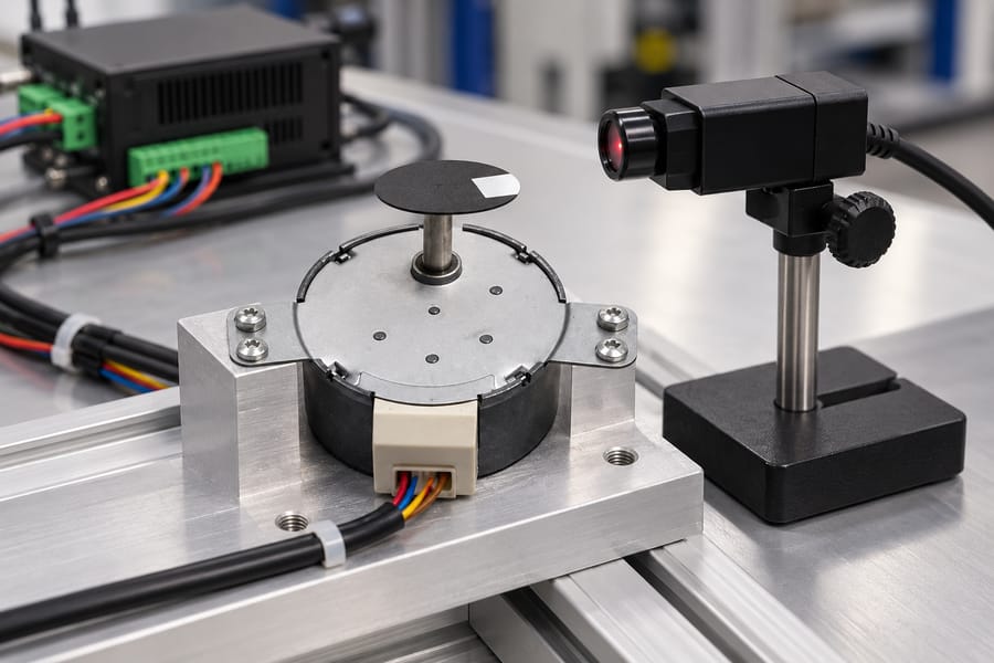
The target output speed is an application requirement, whereas achievable speed depends on the motor, drive, power supply, load, and transmission.
The motor and gearbox must deliver the required output speed and sufficient torque at the same operating point.
A controller may command the calculated motor speed without the motor successfully reaching it. Insufficient torque, excessive acceleration demand, or operating conditions outside the usable torque-speed range can cause stalling or missed steps.
Account for startup, acceleration, deceleration, and any speed changes during the cycle. If the machine requires 60 rpm only during steady operation, the acceleration profile must still allow the system to reach that speed reliably.
Also establish whether the required speed is continuous or intermittent. A motor capable of reaching a particular speed briefly may not sustain the same operating point throughout a demanding production cycle.
Calculate Usable Output Torque at the Required Speed
A gearbox can increase output torque by trading rotational speed for mechanical advantage. However, the useful torque depends on the motor’s actual running torque at the required speed and the gearbox’s transmission efficiency.
For a first-order estimate, use:
Output torque = motor running torque × reduction ratio × gearbox efficiency
Efficiency is expressed as a decimal in this equation. For example, 80% efficiency is entered as 0.80 rather than 80.
The motor running torque must come from an applicable torque-speed curve or validated operating data. The relevant curve should match the selected drive, current settings, supply voltage, and other specified operating conditions.
Holding torque is not a substitute for running torque.
Holding torque describes the motor’s ability to resist rotation when stationary under specified conditions; it does not establish the torque available while the motor rotates at 180, 300, or 480 rpm.
This distinction matters because available stepper torque generally changes with speed. A higher reduction ratio may increase theoretical torque multiplication while forcing the motor into a speed range where its running torque is substantially lower.
The following example illustrates how those competing effects influence ratio selection.
Every motor torque and efficiency value in the table is an explicit assumption for calculation purposes, not a measured torque curve, product specification, or performance claim.
| Reduction ratio | Required motor speed at 60 rpm output | Assumed motor running torque | Assumed gearbox efficiency | Calculated output torque |
| 3:1 | 180 rpm | 0.45 Nm | 85% | 1.1475 Nm |
| 5:1 | 300 rpm | 0.32 Nm | 80% | 1.28 Nm |
| 8:1 | 480 rpm | 0.18 Nm | 72% | 1.0368 Nm |
For the 3:1 candidate, the calculation is 0.45 × 3 × 0.85 = 1.1475 Nm. The 5:1 candidate produces 0.32 × 5 × 0.80 = 1.28 Nm under its separate assumptions.
For the 8:1 candidate, the result is 0.18 × 8 × 0.72 = 1.0368 Nm. Although this candidate has the greatest reduction, its assumed motor torque and efficiency produce less output torque than either alternative.
The example demonstrates why comparing ratios alone is insufficient. A higher ratio may provide greater torque multiplication but deliver less usable output torque if the required motor speed reduces available running torque enough.
The assumed efficiencies also differ deliberately. Actual gearbox efficiency depends on the gearbox design, load, speed, lubrication, and operating conditions; it should not be treated as a universal constant.
When evaluating an actual geared stepper motor, verify that the motor and gearbox combination can meet the required output speed and torque together.
The calculated torque must also cover the application’s demand with an appropriate engineering margin.
Finally, compare usable output torque with the load’s actual requirements, including friction, gravity where applicable, acceleration, and transmission losses beyond the gearbox.
A candidate that meets steady-state torque alone may still fail during startup or rapid changes in speed.
Account for Inertia, Acceleration, and Gearbox Limits
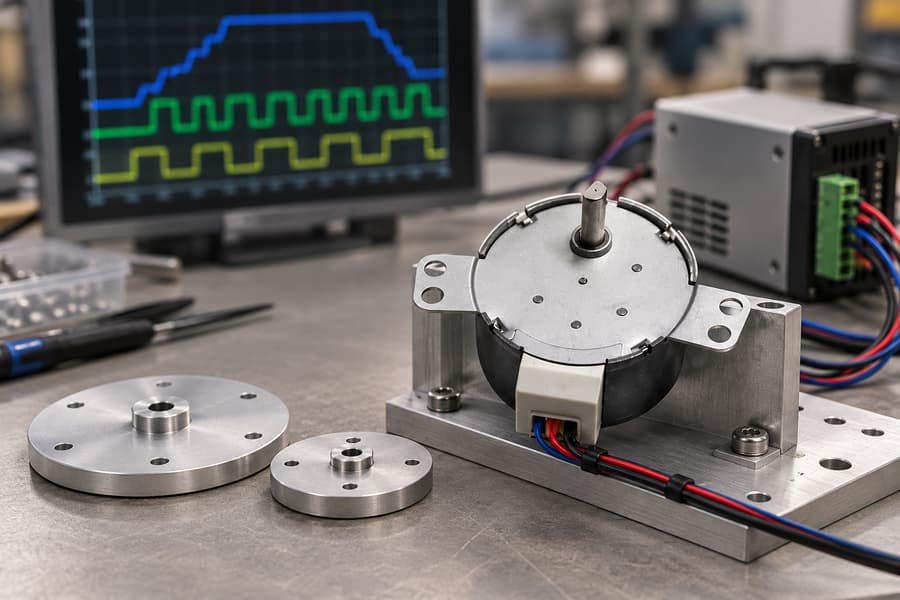
A gear ratio affects more than steady-state speed and torque. It changes the inertia seen by the motor, the acceleration required from the rotor, and the mechanical and electronic limits governing the complete drive system.
Reflect the Output Load Inertia to the Motor Shaft
For an ideal gearbox with reduction ratio i, the output-side load inertia reflected to the motor shaft is calculated as follows:
Reflected load inertia = J_load / i²
Here, J_load represents the total rotational inertia on the gearbox output side, and i is the motor-speed-to-output-speed ratio. This relationship assumes an ideal transmission with a fixed ratio.
For example, a 3:1 reduction reflects one-ninth of the output load inertia to the motor shaft. A 5:1 reduction reflects one-twenty-fifth, while an 8:1 reduction reflects one-sixty-fourth.
Consequently, increasing the reduction ratio can make the driven load appear easier to accelerate from the motor’s perspective. However, this benefit alone does not establish which ratio delivers the best overall performance.
The inertia calculation must include relevant downstream rotating components, couplings, screws, and other mechanisms. Linear masses can also contribute equivalent rotational inertia when their motion is related to shaft rotation through a known transmission geometry.
For an initial comparison, calculate the reflected inertia for each candidate using the same load configuration. Avoid comparing one candidate’s complete mechanism against another candidate’s motor-and-gearbox assembly alone.
Account for Output Acceleration and Motor Rotor Inertia
Although a higher ratio reduces reflected load inertia, it also requires the motor to accelerate faster when the output follows the same acceleration profile. This relationship affects the torque needed during startup and speed changes.
For a fixed reduction ratio, the motor’s angular acceleration is:
Motor angular acceleration = i × output angular acceleration
Suppose a mechanism requires a particular output acceleration. Increasing the ratio from 3:1 to 8:1 makes the motor’s required angular acceleration increase by the ratio of 8/3, assuming the same output acceleration and transmission behavior.
The motor rotor also has inertia, which must be accelerated independently of the external load. Its acceleration torque is calculated using rotor inertia multiplied by motor angular acceleration.
Rotor acceleration torque = J_rotor × motor angular acceleration
Therefore, for the same output acceleration, the motor’s rotor-inertia torque increases in proportion to the reduction ratio. This effect can offset part of the torque benefit obtained by reducing reflected load inertia.
Under an ideal model, the output load’s inertial torque requirement, referred to the motor shaft, decreases with increasing ratio. However, the rotor’s own acceleration demand increases, so the complete torque balance matters.
The motor must provide enough running torque for load acceleration, rotor acceleration, friction, and process forces at the actual instantaneous speed.
A candidate that meets the final-speed torque requirement may still lack sufficient torque during acceleration.
When selecting a stepper motor, consider its available torque across the acceleration profile rather than checking only the starting position or final operating speed.
Account for Gearbox Inertia and Transmission Losses
Gearbox inertia must be included consistently in the mechanical model. Before applying any reflection formula, establish whether the specified inertia is referenced to the input shaft or output shaft.
If gearbox inertia is specified on the input side, add that inertia directly to the motor-side inertia budget.
If it is specified on the output side, reflect it to the motor shaft using the square of the reduction ratio.
For output-referred gearbox inertia, the ideal motor-side equivalent is J_gearbox,out / i². Do not divide an already input-referred inertia by the ratio squared again, because that would underestimate the acceleration demand.
Check the component definition before adding catalog values together. Some specifications may already include particular rotating elements, so confirm the measurement reference and included components before calculating the complete system inertia.
Transmission losses require similar care. If gearbox efficiency has already been applied when calculating the motor torque required for a specified output load, do not apply the same loss allowance a second time.
The ideal inertia-reflection equations do not account for gearbox friction, lubricant behavior, or other real transmission losses. Treat those effects separately using applicable gearbox data or a justified engineering model.
Check Gearbox Input and Output Ratings
The gearbox must satisfy both its input-side and output-side operating limits. A ratio that meets the calculated torque requirement remains unsuitable if its required motor speed exceeds the gearbox’s permitted input speed.
- Input speed: Check the motor’s required operating rpm against the gearbox’s rated input speed and any applicable duty restrictions.
- Input torque: Confirm that the gearbox can accept the motor’s continuous and transient torque demands, including acceleration and deceleration.
- Output torque: Compare the calculated load requirement with the gearbox’s continuous rating and permitted intermittent peak rating.
- Output speed: Confirm that the required speed is compatible with the gearbox’s operating limits under the intended load.
- Thermal duty: Account for operating speed, transmitted torque, cycle duration, starts, stops, and available heat dissipation.
- Backlash: Consider reversal-related lost motion and positioning requirements, particularly when the application repeatedly changes direction.
Continuous torque ratings apply to sustained operation, whereas peak ratings cover permitted short-duration loading under specified conditions.
A short acceleration peak should not be evaluated against a continuous rating alone, nor should an intermittent peak rating be treated as continuously available.
Gearbox thermal capacity also matters when a machine runs repeated cycles. A combination that handles a brief movement may experience excessive heating when the same movement occurs frequently with limited cooling time.
Backlash can affect repeatability and positioning after direction changes. Increasing the reduction ratio does not automatically eliminate gearbox lost motion, so assess the transmission’s mechanical characteristics alongside the motor’s commanded resolution.
Verify Pulse-Frequency and Control Bandwidth
A stepper motor’s required speed must also be achievable within the controller’s pulse-generation capability and the drive’s accepted input frequency. Higher reduction ratios can increase pulse demand even when output speed remains unchanged.
For a hypothetical 1.8-degree stepper motor with 200 full steps per revolution and a setting of 16 microsteps per full step, each motor revolution requires 3,200 command pulses.
At 180 rpm, the pulse rate is 9,600 pulses per second. At 480 rpm, it rises to 25,600 pulses per second, even though both examples could produce the same 60 rpm output with different ratios.
If a hypothetical controller is limited to 20,000 pulses per second, it cannot supply the required 25,600-pulse-per-second command stream. The design would need a compatible pulse source, revised microstepping, or a different operating configuration.
Changing microstepping affects command resolution and pulse demand, but does not guarantee improved absolute positioning accuracy or eliminate the motor’s torque limitations. Any revised setting must remain compatible with the drive and required motion profile.
Validate the Ratio Under Real Operating Conditions
Calculations narrow the candidate ratios, but the selected configuration must also satisfy the machine’s actual motion profile, load variation, thermal duty, and control requirements. Validation should use representative hardware and measurable acceptance criteria.
Establish Representative Load and Motion Conditions
Begin with the real driven mechanism, including its transmission components, payload, friction, and any external forces. Testing an unloaded motor alone cannot establish whether the assembled machine will perform reliably.
Reproduce the required output speed and acceleration profile, including startup, deceleration, direction changes, and positioning pauses. Include the heaviest expected load and other operating conditions that materially affect torque demand.
The test should cover the complete motion cycle rather than only steady rotation. Rapid acceleration may expose insufficient torque, while repeated starts and stops can increase thermal loading beyond that observed during a short demonstration.
Where the machine handles variable products or loads, select representative operating cases and document their differences. If the worst-case load cannot be tested directly, define a justified simulation method and explain its limitations.
Check Torque Margin Across the Operating Profile
Compare the calculated torque demand with the motor’s available running torque at each relevant motor speed. Include acceleration torque, friction, process forces, and transmission losses without counting the same contribution twice.
The pull-out torque curve identifies the boundary beyond which the motor may lose synchronism under specified operating conditions.
A pull-out torque-speed curve indicates the motor’s loss-of-synchronism boundary under stated conditions, not a guaranteed usable range for the complete machine.
Operating close to that boundary leaves little allowance for load variation, temperature changes, supply fluctuations, or mechanical differences. Establish a suitable torque margin using the application’s risk, uncertainty, and required reliability.
Do not apply one universal margin to every stepper application. The acceptable margin depends on the consequences of missed steps, the accuracy of the torque data, and the variability of the actual load.
Compare the Candidate Ratios Against Actual Requirements
The earlier hypothetical comparison favored the 5:1 candidate for calculated output torque under its assumed conditions. That result is provisional because the assumed running torques and efficiencies are not measured data.
The 3:1 candidate requires less motor speed for the same output speed, potentially simplifying pulse generation and preserving more available running torque. However, its greater reflected load inertia may increase motor-side acceleration demand.
The 8:1 candidate reduces the ideal load inertia reflected to the motor shaft, but requires higher motor speed and potentially greater rotor acceleration torque. Its pulse-frequency demand and gearbox input-speed limits also require closer scrutiny.
Recalculate each candidate using the selected motor’s applicable torque-speed data, actual gearbox specifications, and measured or defensibly estimated load characteristics. Retain only configurations that satisfy every critical requirement with an appropriate margin.
Verify Thermal Duty and Control Behavior
Run the machine through its intended continuous and intermittent operating cycles. Include dwell periods, repeated acceleration, and realistic pauses because these influence motor heating, gearbox losses, and available cooling time.
Measure motor and gearbox temperatures at documented locations using a consistent method. Continue testing until temperatures stabilize or the specified duty period is completed, and compare readings with the applicable component limits.
Check that the controller supports the necessary pulse rate at every commanded speed, including the highest operating point. Check pulse scaling, microstepping settings, acceleration commands, and the relationship between commanded movement and actual output displacement.
If power interruption or restart is relevant, test the expected recovery sequence under controlled conditions.
Establish whether the mechanism must retain position, return to a reference, release a load safely, or require re-homing before production resumes.
Document the Acceptance Criteria
Define the pass conditions before testing begins. Criteria should reflect the machine’s required throughput, positioning performance, load capacity, operating environment, and applicable component ratings rather than arbitrary universal tolerances.
| Verification item | Measurement or test | Machine-specific acceptance criterion |
| Output speed and torque | Measure speed and confirm performance under representative load | Required speed achieved without stalling or unacceptable speed deviation |
| Acceleration and positioning | Record motion profile, settling behavior, and position error | Application-defined acceleration, settling, and positioning requirements met |
| Torque margin | Compare demand with applicable torque-speed data | Agreed margin maintained across critical operating points |
| Thermal duty | Record motor and gearbox temperatures during representative cycles | Temperatures remain within documented limits |
| Pulse generation | Check command frequency, scaling, and achieved movement | Controller and drive remain within specified limits; commanded motion is reproduced |
| Power interruption, if relevant | Interrupt power and execute the specified recovery sequence | Required recovery, reference, and load-control behavior demonstrated |
Repeat critical tests to identify inconsistent results, missed steps, unexpected heating, or positioning drift. Record the load, speed, acceleration settings, supply conditions, measurement method, and component temperatures for each test.
Record the Selected Configuration and Acceptance Evidence
The final selection record should identify the motor and gearbox models, reduction ratio, applicable torque-speed data, driver settings, supply conditions, pulse scaling, and required output performance.
Include gearbox input and output ratings, reflected-inertia calculations, acceleration assumptions, thermal-duty conditions, and the agreed torque margin. Record any limits on continuous operation, peak loading, or restart behavior.
Retain test results, measured values, deviations, corrective actions, and approval against each acceptance criterion.
The approved configuration should be traceable to the tested hardware and settings, with documented evidence that the complete machine meets its required operating conditions.