
A PM stepper valve actuator needs a reliable physical reference to establish its actual mechanical position. Commanded step counts alone cannot confirm movement or identify accumulated positioning errors.
Reliable homing combines suitable reference detection, controlled movement, startup checks, and repeatability testing. Engineers must also protect valve components and define recovery behavior when reference detection fails.
Why Does a PM Stepper Valve Actuator Need a Physical Reference Position?
Commanded Step Count Versus Actual Mechanical Position
A PM stepper valve actuator moves through discrete motor steps, allowing a controller to estimate linear displacement from a known starting position. However, commanded movement and verified mechanical movement are not necessarily identical.
The controller typically calculates position by accumulating commanded pulses. This method assumes that the rotor follows the requested sequence and that the transmission converts rotation into predictable linear displacement.
Several conditions can invalidate this assumption. Excessive mechanical loading, insufficient available torque, acceleration demands, and unexpected friction can cause missed steps or incomplete movement.
Mechanical backlash also affects positioning accuracy. When the direction changes, the motor may rotate through transmission clearance before the output mechanism begins moving.
Coupling looseness, transmission wear, and mechanical slip introduce additional differences between the controller’s estimated coordinate and the actuator’s actual position. These errors may accumulate without generating an obvious control fault.
What Does a Reference Position Establish?
Homing identifies a defined physical position through an appropriate detection method. Once the reference event is confirmed, the controller assigns a corresponding coordinate to the actuator.
Homing may be necessary during initial commissioning, after controller resets, following power interruptions, or whenever the system cannot confidently retain its previous position.
The required initialization strategy depends on the feedback architecture. An incremental position system generally needs a physical reference, while an appropriately configured absolute encoder may retain usable position information.
What Homing Cannot Confirm
A reference position establishes actuator position, not complete valve performance. Reaching a designated closing coordinate does not prove that the valve has achieved an acceptable sealing condition.
Shutoff leakage depends on valve construction, seat condition, sealing materials, differential pressure, and other application conditions.
Similarly, actuator position alone cannot establish actual flow rate or pressure-control accuracy. These characteristics require separate measurements and application-specific acceptance procedures.
Which Reference Methods Can a PM Stepper Valve Actuator Use?
The appropriate reference method depends on the actuator’s mechanical arrangement, available feedback hardware, environmental conditions, and required positioning repeatability.
Engineers should distinguish dedicated position detection from protective travel limitation. These functions may use separate devices even when both respond to actuator movement.
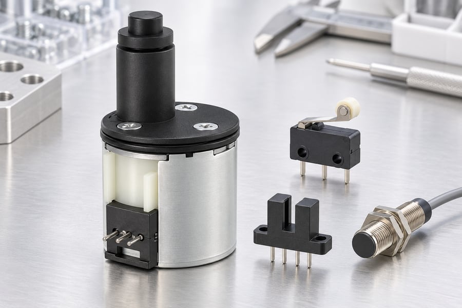
Dedicated Homing Sensor
A dedicated homing sensor detects a defined physical location without necessarily requiring mechanical contact. Depending on the design, sensing may use magnetic, optical, inductive, or other suitable detection principles.
The sensor needs a stable mounting position in relation to the actuator’s moving parts. Mounting movement, contamination, temperature variation, and electrical interference can change detection behavior.
The sensor’s electrical output must also match the controller input requirements. Signal polarity, wiring arrangement, voltage compatibility, and fault-detection provisions should be confirmed during system integration.
Travel Switch
A travel switch identifies a defined mechanical boundary through physical actuation. It can provide a useful reference signal when its mounting location and switching behavior are sufficiently repeatable.
However, switch actuation depends on mechanical contact geometry, operating force, mounting stiffness, and contact condition.
Repeated operation may also introduce wear or changes in switching behavior. Engineers should therefore distinguish a protective limit switch from a sensor specifically selected for precision homing.
Where one switch performs both functions, the control strategy must account for the different requirements of reference acquisition and overtravel protection.
Encoder-Based Referencing
Incremental encoders provide movement information through pulse signals. However, their accumulated position count may not identify an absolute mechanical origin after power loss or controller initialization.
An index event needs a known relationship to the output position. A once-per-revolution motor index cannot by itself distinguish different screw revolutions; use a coarse reference or another validated way to identify the correct turn.
Absolute encoders provide position information relative to their defined measurement range. Depending on their architecture, they may eliminate the need for a conventional search after startup.
Nevertheless, absolute position information is only useful when its validity, mechanical coupling, and retention behavior are established.
Mechanical-Stop Referencing
A mechanical stop can establish a reference through controlled contact with a suitable structural boundary. This approach requires careful consideration of impact energy, contact force, material compliance, and mechanical durability.
A stop must be designed and approved for the intended homing operation. Engineers should obtain the supplier’s permitted contact-force and energy limits before implementing this method.
An actuator must never repeatedly drive into a fragile valve seat to establish its reference. Excessive contact can damage sealing surfaces, deform components, or change subsequent positioning behavior.
Comparing Reference Methods
| Method | Main advantage | Main limitation | Engineering consideration |
| Homing sensor | Detects a defined physical location | Detection and mounting variation | Signal stability and repeatability |
| Travel switch | Provides a recognizable travel boundary | Contact wear and actuation variation | Separate reference and protection requirements |
| Incremental encoder | Tracks movement and displacement | Usually requires initial referencing | Index detection and position retention |
| Absolute encoder | Provides absolute position information | Depends on architecture and coupling integrity | Data validity after power interruption |
| Mechanical stop | Establishes a physical boundary | Contact loads and structural variation | Supplier-approved force and energy limits |
How Should a Reliable PM Stepper Valve Actuator Homing Sequence Work?
A reliable homing routine should follow a defined sequence rather than immediately driving the actuator toward an assumed endpoint. Startup validation, bounded searching, controlled detection, and fault handling are essential.
Step 1: Check the Startup State
Before enabling homing movement, the controller should verify its initialization state and confirm that the driver is ready to operate.
The controller should inspect available sensor and travel-switch inputs for plausible combinations. Unexpectedly active signals, disconnected wiring, and contradictory limit states require investigation.
An initially active homing sensor deserves particular attention. The controller should determine whether the actuator is already within the detection region or whether the signal indicates a wiring or sensor fault.
If the actuator starts inside the active region, the recovery strategy may require controlled movement away from the sensor before another reference search. Such movement must remain within verified mechanical travel boundaries.
The controller must also determine whether previously stored position information is trustworthy. An unknown or potentially invalid coordinate should not be treated as a confirmed starting position.
Step 2: Perform a Bounded Position Search
The search direction should be established from the mechanical layout and valve travel arrangement. Engineers must confirm that the selected direction moves toward the intended reference without creating an unsafe condition.
Maximum search distance and maximum homing time should be independently defined. Either limit must terminate the search when the expected reference event does not occur.
A missing sensor signal must not cause the actuator to continue moving indefinitely. Likewise, a travel limit reached before the expected reference event should trigger a defined fault response.
Step 3: Acquire the Reference Edge
Once the actuator approaches the expected detection region, the controller should reduce movement speed to improve reference acquisition.
Switch debounce and slow edge acquisition solve different problems. Debounce rejects short electrical transitions caused by contact bounce or signal instability.
Slow approach controls mechanical movement so the detected edge corresponds more consistently to the physical reference. Increasing debounce time cannot compensate for excessive approach speed or inconsistent mechanical motion.
The controller should define whether the reference is the sensor’s activation edge, release edge, or another specified transition. The chosen event must remain consistent across commissioning and normal homing.
Step 4: Back Off and Re-Approach
After initial detection, the actuator should move away from the sensor by a controlled distance. This backoff allows the sensor to return to its inactive state before final reference acquisition.
The controller must verify that the signal actually clears. If the sensor remains active after the permitted backoff movement, the sequence should stop and identify the condition as a fault.
Once the signal clears, the actuator can approach again at reduced speed. Using a consistent final approach direction helps reduce backlash and direction-dependent positioning variation.
Step 5: Assign the Reference Coordinate
The controller should assign the reference coordinate only after the required detection sequence has completed successfully.
It should verify that the detected position is plausible relative to the permitted actuator travel and the expected sensor arrangement.
A successful reference event does not independently establish valve closure quality. Valve sealing and process performance remain separate verification activities.
Step 6: Handle Failed Homing
A failed search should produce a defined response rather than another unrestricted movement command. Retry limits must be established according to the mechanical and control-system requirements.
The controller should distinguish between missing sensor signals, an initially active sensor, failure to clear during backoff, unexpected travel direction, and maximum-distance or timeout violations.
The following table summarizes the main sequence and corresponding fault responses.
| Homing stage | Required action | Failure condition and response |
| Startup checks | Verify driver readiness and input states | Reject contradictory or implausible sensor states |
| Initial sensor check | Determine whether the sensor is already active | Apply a verified recovery strategy or enter a fault state |
| Bounded search | Move toward the reference within defined limits | Stop on maximum distance or time expiration |
| Edge acquisition | Reduce speed and detect the specified transition | Reject unstable or missing reference signals |
| Backoff | Move away until the sensor clears | Stop if the signal remains active within permitted travel |
| Re-approach | Acquire the reference from a consistent direction | Reject inconsistent or unexpected transitions |
| Coordinate assignment | Establish the reference after successful detection | Retain the fault state if position confirmation fails |
| Recovery | Apply bounded retries and defined reset conditions | Require inspection or authorized recovery when unsuccessful |
Retries should not conceal a persistent mechanical or electrical problem. After the permitted attempts are exhausted, the controller should prevent normal positioning commands until the application-specific recovery conditions are satisfied.
What Factors Affect Homing Reliability Under Actual Valve Operating Conditions?
A homing routine may perform consistently during initial testing but produce different results when valve loading, temperature, friction, and electrical conditions change.
Sensor Hysteresis and Electrical Interference
Sensor hysteresis describes the difference between activation and release positions. A sensor may therefore switch off at a different mechanical location from where it originally switched on.
This behavior matters when the homing sequence uses different transitions or approaches the sensor from inconsistent directions.
Electrical interference can also produce false transitions. Motor switching activity, cable routing, grounding arrangements, and signal connections may influence sensor reliability.
Debounce delay also creates travel between the physical edge and accepted signal; at constant speed that distance is speed multiplied by delay. Reject brief unwanted transitions without excessive detection delay. Its settings must reflect the actual signal characteristics and controller sampling behavior.
Filtering should not become a substitute for sound electrical design. Stable wiring, appropriate input conditioning, and secure sensor mounting remain important.
Why Motor Current Alone Cannot Reliably Identify a Mechanical Stop
Stepper motor drivers commonly regulate winding current to control motor operation. However, maintaining the commanded current does not establish that the rotor or actuator is moving.
When a current-regulated drive encounters an obstruction, the regulated current may remain close to its commanded value. The controller may therefore receive no definitive indication that the actuator has stalled.
Back electromotive force, winding characteristics, drive behavior, and measurement methods influence whether a stall can be inferred from electrical signals.
If stall detection is required, engineers should evaluate appropriate feedback or dedicated detection methods. Encoder information, sensor signals, and validated drive diagnostics may contribute to a suitable strategy.
Valve Pressure, Stiction, and Seal Wear
Valve loading varies with differential pressure, flow conditions, and mechanical construction. Consequently, the actuator may encounter different resistance during opening and closing.
Static friction can make initial movement more demanding than continued travel. Seal wear, contamination, lubrication changes, and material aging may further alter resistance.
A homing reference should therefore rely on a defined detection method rather than assuming that a particular resistance level always represents the same physical position.
Temperature, Speed, and Mechanical Variation
Temperature changes can influence mechanical dimensions, lubricant behavior, friction, and sensor characteristics. Testing only under one laboratory condition may overlook relevant operating variation.
Homing speed also matters. Excessive speed can increase contact energy and reduce the consistency of mechanical reference acquisition.
Backlash, transmission compliance, coupling looseness, and mounting movement introduce additional uncertainty. These factors should be evaluated during system validation rather than compensated for through repeated uncontrolled homing attempts.
How Can Engineers Validate Homing Repeatability and Position Retention?
Homing reliability should be demonstrated through physical measurements and documented operating tests. A controller reporting the same coordinate after every cycle does not independently prove that the actuator reaches the same physical location.
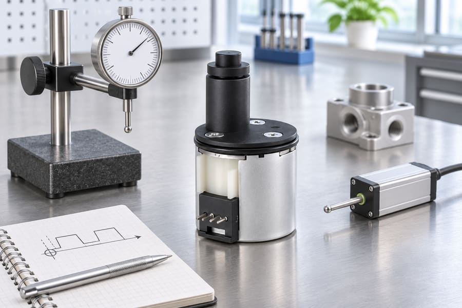
Establish a Physical Repeatability Test
Engineers should first define the reference point and an appropriate measurement method. The measurement boundary must distinguish actuator output displacement from motor rotation or controller pulse count.
Repeated homing cycles should begin from different initial positions within the permitted travel range. This helps determine whether the search routine consistently identifies the same physical reference.
The final mechanical position should be recorded for every cycle. Results can then be compared against application-defined repeatability requirements.
Measurements should also identify the detection direction and the sensor transition used. Without this information, results from different test procedures may not be directly comparable.
Validate Across Operating Conditions
Testing should cover representative operating temperatures and mechanical loads. Where relevant, engineers should evaluate the effects of valve pressure and differences between opening and closing resistance.
Sensor activation, release behavior, and backoff clearance should be recorded. Repeatedly successful detection under one condition is insufficient evidence if the application experiences substantially different loads or temperatures.
Verify Position Retention After Power Loss
Position retention requires particular attention when the actuator uses incremental movement tracking. A controller may preserve its previous coordinate even though the mechanical output has moved while power was unavailable.
Potential causes include external loading, back-driving, transmission movement, and coupling slip.
Engineers should test the complete assembly through representative shutdown and restart conditions. They must determine whether the stored coordinate remains trustworthy or whether a new homing cycle is necessary.
Define Acceptance and Failure Behavior
Acceptance criteria should specify allowable physical reference variation, permitted startup conditions, and the expected response to unsuccessful detection.
The commissioning record should identify search limits, timeouts, retry limits, sensor transitions, and recovery procedures. These values must come from the actual application requirements rather than assumed universal settings.
Homing acceptance must remain separate from valve functional acceptance. Leakage testing, flow measurement, and pressure-control verification require their own methods and criteria.
How Should Engineers Evaluate Leili Motor PM Stepper Actuators for Reliable Homing?
Match the Actuator to Valve Requirements
Start by identifying the required stroke, mechanical interface, travel boundaries, and expected operating loads. Valve pressure, seal resistance, and changing friction should also be considered.
The 25BY412 PM stepper linear actuator for valve control provides a relevant product reference when evaluating PM stepper linear actuation.
However, engineers should not assume that this product includes an integrated homing sensor, encoder, or particular internal position-feedback architecture. Such capabilities must be confirmed against the actual product configuration.
Evaluate Motor and Driver Compatibility
Current regulation, voltage headroom, winding characteristics, and available torque influence movement behavior. Engineers should avoid treating commanded current as proof of rotor movement or mechanical stall detection.
Leili Motor’s permanent magnet stepper motor options provide a starting point for matching winding and mechanical interfaces to the selected driver and valve mechanism.
Define the Complete Homing Configuration
If mechanical-stop referencing is proposed, obtain supplier approval for the permitted contact force and energy. Confirm that the arrangement cannot damage the valve seat or other vulnerable components.
Commissioning Evidence and Supplier Questions
A useful commissioning package should contain the following evidence:
- Homing configuration:
Sensor type, mounting arrangement, signal polarity, and reference transition. - Sequence parameters:
Search direction, approach speed, maximum travel, timeout, and retry limits. - Repeatability results:
Recorded physical reference positions across repeated cycles and representative operating conditions. - Electrical verification:
Input stability, debounce settings, wiring checks, and relevant driver behavior. - Power-loss testing:
Evidence supporting retained position validity or the required re-homing procedure. - Fault recovery:
Recorded responses to missing signals, initially active sensors, unsuccessful backoff, and search-limit violations. - Mechanical protection:
Confirmation that homing loads remain within approved actuator and valve limitations.
Before finalizing the design, engineers should ask the supplier whether the selected actuator supports the intended external sensor arrangement, what mechanical loads are permitted during referencing, and whether position feedback is integrated or separately required.