
A liquid cooling loop for an axial flux motor should be specified through the conditions it must deliver at the motor connections, not through the cooling unit’s headline capacity alone. The acceptance plan should confirm inlet temperature, flow, pressure conditions, fluid compatibility, and the response to loss of cooling. These requirements must be agreed with the motor supplier for the exact operating duty.
Where Should the Cooling Specification Begin?
Begin at the motor’s cooling interface and work outward to the complete circuit. Ask what conditions the selected motor requires during continuous operation and any approved temporary demand. The cooling equipment can then be assessed against those conditions under the machine’s expected ambient and simultaneous loads.
For a liquid-cooled model within the Leili axial flux motor range, request the applicable fluid, temperature, flow, and pressure requirements in writing. A family-level statement that a motor is water cooled does not define a complete installation specification. The selected model’s documentation should govern the design.
State which organization owns the loop design, supplies each component, and validates the assembled circuit. The motor manufacturer, cooling equipment supplier, and machine integrator may each provide only part of the information. A responsibility list prevents gaps at their interfaces from appearing during commissioning.
Which Conditions Must Be Defined at the Motor Connections?
Define the required inlet condition, allowed outlet condition where applicable, flow range, pressure limits, and permitted pressure drop using the supplier’s terminology. Identify the location at which each requirement applies. A measurement at a remote cooling unit may not represent the condition at the motor after intervening pipework and components.
Fluid specification needs more detail than a casual description such as clean water. Material compatibility, required treatment, and any permitted mixture should come from the equipment suppliers. Do not select additives or concentrations from a general motor article because the wetted materials and operating conditions may differ.
| Item | Specification Question | Acceptance Evidence |
| Inlet temperature | What range applies at the motor? | Reading under representative load |
| Flow | What operating range is permitted? | Verified branch measurement |
| Pressure | Which limits and locations apply? | Documented operating readings |
| Fluid | What composition is approved? | Supplier and fill records |
| Protection | What response follows lost cooling? | Approved functional verification |
Document the operating condition associated with every reading. Flow measured when only one branch is active may not establish the motor’s available flow when other equipment shares the circuit. Include the simultaneous demand expected during normal production.
How Can a Heat Balance Help Evaluate the Circuit?
A heat balance can support the assessment when flow, fluid properties, and inlet-to-outlet temperature difference are known with suitable accuracy. For a liquid stream, heat transport is commonly estimated from mass flow multiplied by specific heat capacity and temperature rise. The result concerns heat carried by that stream, not automatically all losses in the motor or system.
As a hypothetical arithmetic example, 0.1 kg/s of water with an assumed specific heat of 4.18 kJ/(kg·K) and a 5 K rise carries approximately 2.09 kW. The calculation assumes those values are appropriate and sufficiently steady. It is not a Leili heat-rejection specification or a recommended coolant flow.
Interpret a small measured temperature difference cautiously when measurement uncertainty is significant relative to that difference. Sensor placement, synchronization, and calibration affect the result. NIST guidance on measurement uncertainty and method definition supports documenting the method rather than treating repeatable readings as complete proof of accuracy.
Why Can Adequate Cooling-Unit Capacity Still Leave the Motor Undersupplied?
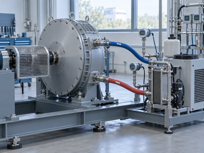
The cooling unit’s capacity does not establish the flow and temperature delivered through the installed circuit. Pipework, fittings, filters, shared branches, and operating controls affect the motor’s actual service. Check the path from the cooling unit through the installed branches to the motor, because component ratings alone do not establish the service arriving at that connection.
Pressure drop and available pump performance must be assessed together by the cooling-system designer. A branch can receive less flow than expected even when the overall unit appears correctly sized. The acceptance plan should therefore verify the relevant branch conditions instead of relying only on a central display.
Leili’s overview of air and liquid cooling for axial flux motors provides background on the available approaches. This project-specific review begins after the cooling method has been chosen. Its purpose is to prove that the chosen method is implemented under the conditions used to establish the motor’s duty capability.
What Should Be Checked About Routing and Connections?
Check that the hoses or pipes, fittings, supports, and connection orientation follow the approved design and equipment instructions. Allow access for inspection and the required service tasks. A compact motor arrangement can lose its packaging advantage when cooling connections have to be rerouted after the machine is built.
The published Leili 30 kW axial flux motor page includes both air-cooled and water-cooled variants. The selected variant must therefore be identified before interface drawings and cooling equipment are released. A shared power rating is not sufficient to infer connection geometry or required services.
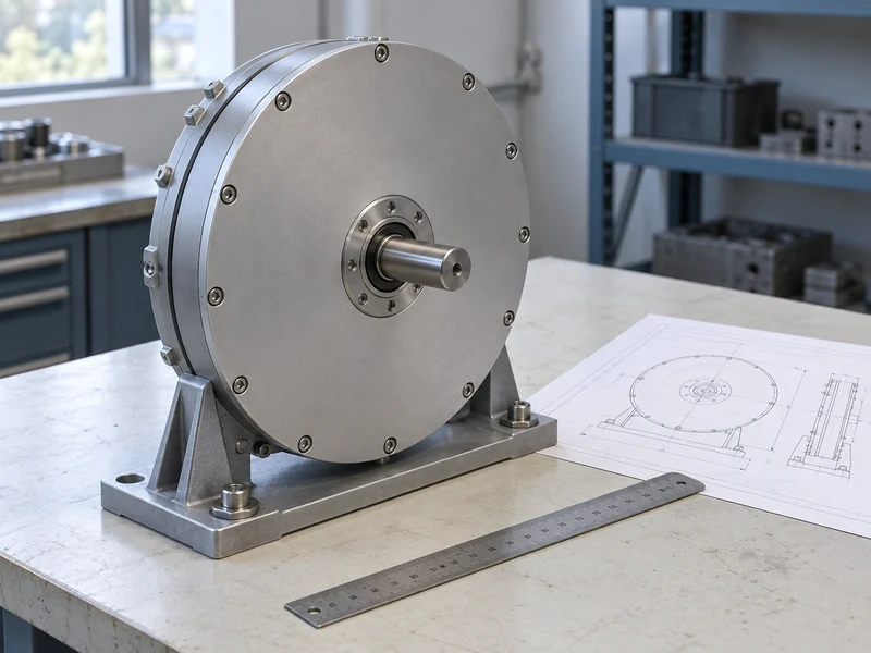
Keep the cooling design connected to the mechanical integration review. A hose route should not obstruct coupling access, guard removal, or the approved lifting path. The existing article on axial flux motor integration with transmissions and direct-drive systems provides related context for considering these interfaces together.
How Should Loss of Cooling Be Addressed?
The machine specification should define the protective response to inadequate cooling according to the motor supplier’s limits and the machine’s operating requirements. Identify the sensors used, their locations, and the actions associated with a warning or fault. A cooling pump running signal does not necessarily prove that sufficient flow reaches the motor.
Functional verification should follow an approved procedure that does not expose the motor or process to an uncontrolled condition. The purpose is to confirm the signal chain and intended response, not to improvise a destructive thermal test. Assign responsibility for the procedure to the appropriate engineering team.
Restart conditions should also be agreed. Restored flow alone may not establish that every requirement for operation has been met after an interruption. Use the supplier’s guidance and machine control design to define the permitted recovery sequence.
Which Records Should the Acceptance Report Preserve?
Preserve the circuit revision, component identification, approved fluid information, instrument details, and readings under the agreed operating states. Record ambient and load conditions so that future investigations have a meaningful reference. Photographs or diagrams of measurement locations can help another engineer reproduce the test.
Where the motor’s design or manufacturing configuration influences the cooling arrangement, retain the relevant supplier documentation with the asset record. Leili’s article on the axial flux motor manufacturing process gives background, while the delivered model’s drawings and instructions provide the controlling information. Do not substitute a general manufacturing description for the actual connection and service requirements.
List exceptions separately from passed checks. An unresolved temperature reading or an unverified shared-load condition should have an owner and a closure requirement. This avoids a general commissioning sign-off concealing a cooling condition that has not yet been demonstrated.
What If a Shared Circuit Passes One Test but Fails Another?
Investigate the operating context before assuming the motor has changed. In a hypothetical machine, the motor branch may receive adequate cooling when tested alone, then experience a different inlet temperature or flow when another load joins the circuit. Comparing the two records should reveal which service condition changed.
The circuit designer should review the actual simultaneous loads, control states, and measured branch conditions. Do not respond by increasing a pump setting without checking the permissible pressure and flow limits of all affected equipment. The corrective proposal should explain how the revised circuit meets the motor requirement under the demanding normal operating case.
Repeat the affected acceptance checks after an approved change and preserve the earlier results. A clear record helps maintenance recognize the same pattern later if a filter, valve position, or operating schedule changes. It also prevents a central cooling-unit reading from becoming the sole indicator of service quality at every connected motor.
What Makes the Cooling Loop Ready for Production?
The loop is ready when it delivers the agreed services at the motor, the protective functions have been verified, and the operating and maintenance requirements are documented. The acceptance conclusion should be tied to the tested configuration and duty. Future changes to fluid, pipework, shared loads, or production demand should trigger a review of that basis.
This approach makes cooling performance visible at the point where the motor depends on it. It also gives the plant a useful reference for distinguishing a motor problem from a change in the supporting circuit. The result is a cooling specification that can be verified and maintained rather than a nominal capacity written on a purchase order.