
Can-stack and disc-magnet permanent magnet (PM) stepper motors use different magnetic and mechanical constructions, creating distinct packaging considerations. Their suitability depends on more than external dimensions or rotor shape.
Engineers must evaluate installation space, rotor inertia, mechanical interfaces, thermal paths, driver compatibility, and dynamic performance together. Understanding these factors helps identify the architecture that best fits an application.
Can-Stack vs Disc-Magnet PM Stepper Motors: Structural and Magnetic Differences
The main distinction between can-stack and disc-magnet PM stepper motors lies in their magnetic circuit and internal component arrangement. These differences influence how the rotor, stator, and supporting structures occupy the available space.
Can-Stack PM Stepper Motor Construction
A typical can-stack PM stepper motor uses two claw-pole stator assemblies arranged around a cylindrical permanent magnet rotor. The stator modules contain formed magnetic pole structures that interact with the rotor’s magnetic field.
The claw-shaped poles extend around the rotor, creating alternating magnetic pole regions. When the stator windings receive appropriately sequenced electrical pulses, their magnetic fields produce incremental rotor movement.
The stacked metal housing encloses and supports the internal assembly. Its cylindrical body provides a recognizable packaging arrangement, although actual dimensions and internal details vary between designs.
The rotor, stator modules, windings, shaft, and supporting components collectively determine the motor’s mechanical configuration. Their arrangement affects the available mounting surfaces, shaft position, and overall installation envelope.
Disc-Magnet PM Stepper Motor Construction
A disc-magnet PM stepper motor uses a thin permanent magnet disc with multiple magnetic poles. Its magnetic geometry differs from the cylindrical rotor commonly associated with can-stack construction.
The magnet disc interacts with the stator’s electromagnetic field to generate incremental rotation. The specific arrangement of magnetic poles, stator components, and air gaps depends on the motor design.
A disc-shaped magnet does not automatically establish the complete motor’s orientation or magnetic operating principle. Engineers should distinguish rotor geometry from assumptions about the direction of magnetic flux.
The disc magnet’s thickness and diameter influence the available magnetic and mechanical packaging space. However, the complete assembly also requires suitable shaft support, stator structures, and mounting provisions.
Understanding Architecture and Product Terminology
Construction terminology sometimes overlaps with commercial product classifications. A manufacturer may describe a motor using a packaging category even when its internal design requires additional clarification.
For example, claw-pole construction and can-stack packaging are closely associated, but the terms do not necessarily describe every aspect of an individual motor. Similarly, disc-magnet classification alone does not establish all details of its magnetic circuit.
Leili Motor lists claw-pole, disc-magnet, and can-stack designs within its permanent magnet stepper motor categories. These categories offer an initial reference for evaluating the available motor constructions.
For an engineering evaluation, the sectional drawing should establish the actual rotor orientation, stator arrangement, air gap, shaft configuration, and supporting components. This prevents selection decisions based on product names alone.
Axial Length vs Radial Diameter: Comparing the Installation Envelope
Packaging decisions often begin with two fundamental dimensions: axial length and radial diameter. Their relative importance depends on the available equipment space and the surrounding mechanical arrangement.
Understanding Axial and Radial Packaging
Axial length describes the motor’s dimension along its rotational axis, while radial diameter describes its maximum dimension perpendicular to that axis.
A can-stack motor’s cylindrical housing establishes a relatively straightforward external envelope. Its axial dimension includes the stacked housing and other projecting components, depending on the measurement reference.
Disc-magnet construction uses a different rotor geometry, but this does not guarantee a shorter complete motor. Stator thickness, supporting structures, shaft arrangements, and mounting features still contribute to installed dimensions.
A thin magnetic disc may reduce the axial space occupied by the rotor itself. Nevertheless, the complete motor could require additional space for its supporting and electromagnetic components.
The comparison should therefore distinguish rotor thickness, active magnetic assembly dimensions, housing dimensions, and overall installed length. Each dimension describes a separate installation constraint, so each should be assessed independently.
Consider the Complete Motor Installation Space
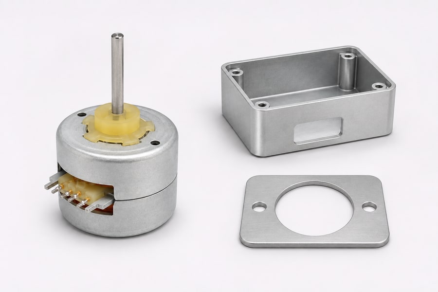
External motor dimensions rarely represent the entire space required by an integrated mechanism. Shaft projection, mounting plates, fasteners, and electrical connections can extend beyond the nominal housing envelope.
Connector orientation deserves particular attention in compact assemblies. A motor may fit within the available body dimensions but become difficult to install when its connector faces an enclosure wall.
Cable clearance also requires consideration. Wiring needs sufficient space for its intended routing and bend radius without interfering with moving components or adjacent structures.
Mounting pilot dimensions and fastener access can influence the surrounding bracket design. Engineers should check whether the selected mounting arrangement provides sufficient clearance for assembly tools and future maintenance.
A useful comparison separates the motor’s external envelope from its complete installation envelope. The latter includes every component and clearance necessary for the intended mechanical and electrical connections.
Select According to Application Geometry
Different equipment layouts create different dimensional priorities. An instrument with restricted axial depth may favor a motor configuration that satisfies its length limit without exceeding the available radial space.
Conversely, a mechanism installed inside a narrow cylindrical housing may have a strict diameter limit but sufficient axial clearance. In this situation, radial packaging becomes the dominant selection constraint.
The orientation of neighboring components also matters. A motor that fits dimensionally may still create difficult routing or assembly conditions when its shaft, connector, or mounting features face inaccessible directions.
Engineers should compare candidate motors against the actual equipment layout rather than selecting an architecture based on a general compactness claim. A complete dimensional drawing provides the necessary reference for this evaluation.
Rotor Inertia and Mechanical Integration: Shaft, Bearings, and Mounting
External dimensions describe how much space a motor occupies, but they do not establish how its rotor behaves mechanically. Rotor inertia, bearing support, shaft geometry, and mounting conditions influence integration and motion response.
Rotor Inertia and Its Effect on Motion
Rotor inertia describes the resistance of a rotating component to angular acceleration. Rotor inertia is governed by the rotor’s total mass and the radial position of that mass relative to its axis.
For a simplified rigid body, mass located farther from the axis contributes more strongly to rotational inertia than the same mass concentrated near the center. Consequently, rotor diameter and material distribution matter alongside total mass.
A disc-shaped rotor is not automatically lower in inertia than a cylindrical rotor. Its actual inertia depends on its diameter, thickness, material density, hub arrangement, and other rotating components.
Similarly, two motors with comparable external dimensions may have substantially different rotor inertia. Their internal mass distribution and shaft arrangements can differ even when their housings appear similar.
This distinction becomes important in applications requiring frequent starts, stops, and direction changes. Higher combined inertia generally requires greater torque to achieve the same angular acceleration under otherwise equivalent conditions.
Engineers should obtain the rotor inertia specification when acceleration performance matters. They should also account for reflected load inertia from couplings, gears, pulleys, and driven mechanisms.
Shaft and Bearing Arrangements
Shaft configuration determines how the motor connects mechanically to the driven equipment. Diameter, extension length, end geometry, and available engagement length influence coupling selection and installation.
Bearing arrangements establish how the rotating assembly is supported. Their configuration affects permissible radial and axial loads, shaft movement, and mechanical stability.
A motor’s internal bearings should not automatically be considered suitable for every external loading condition. Belt tension, overhung pulleys, axial thrust, and misaligned couplings can impose loads beyond the intended support arrangement.
Engineers should examine the specified bearing load limits and shaft support details. Where the driven mechanism introduces substantial external loading, the overall support arrangement may need to carry those loads independently.
The relationship between shaft projection and bearing position also deserves attention. A longer unsupported shaft extension can increase bending sensitivity when external forces act away from the supporting bearing.
Mounting Interfaces and Mechanical Alignment
Mounting geometry affects how accurately the motor integrates with the surrounding equipment. Pilot diameter, mounting-face flatness, fastener locations, and seating surfaces should match the corresponding bracket or housing.
Bracket stiffness also influences operating behavior. A flexible mounting structure may transmit vibration differently from a rigid support, potentially affecting resonance and positioning consistency.
Shaft alignment is equally important. Angular or parallel misalignment can introduce additional bearing loads, coupling forces, and vibration during operation.
For disc-magnet and can-stack designs, the relevant mounting considerations depend on their actual mechanical interfaces rather than their architectural labels. Engineers should verify the mounting arrangement using the manufacturer’s drawing.
A complete integration review should consider the motor, coupling, driven load, and support structure as one mechanical system. Evaluating these components independently can overlook interactions that affect actual performance.
Thermal Performance: Heat Dissipation in the Installed Assembly
Thermal performance depends on heat generation and the ability of the complete assembly to transfer that heat into its surroundings. Motor architecture influences the available heat paths, but does not independently determine operating temperature.
Identify the Main Sources of Motor Heating
Winding copper losses are an important source of heat in PM stepper motors. As current passes through a winding, its electrical resistance causes some input energy to be released as heat.
Other losses may also contribute, depending on the magnetic design, electrical excitation, and operating conditions. Their relative importance varies between motor configurations.
Operating current and duty cycle influence the thermal load. A motor that frequently holds position under energized conditions may experience a different heating profile from one operating intermittently.
Stepping frequency and load conditions also affect the operating state. Therefore, comparing two motors using only their rated current or nominal voltage provides an incomplete thermal assessment.
The distinction between heat generation and heat dissipation is essential. A motor may generate similar internal losses to another design but reach a different temperature because its thermal path differs.
Compare Thermal Paths and Mounting Conditions
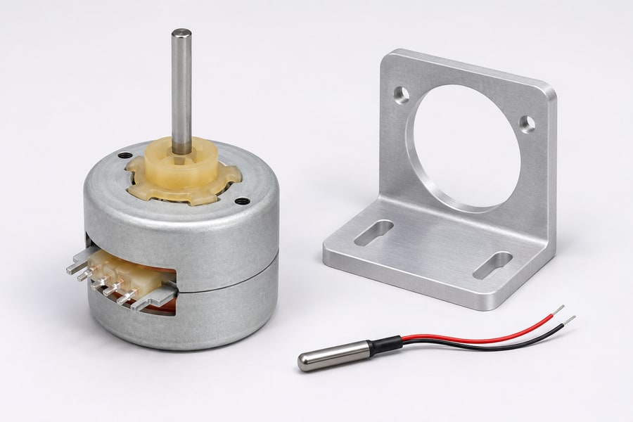
Heat must travel from the windings and stator structures toward surfaces that can release it into the surrounding environment. The available path depends on internal construction, housing materials, contact surfaces, and assembly geometry.
Mounting brackets can form an important part of this thermal path. A suitable contact interface may transfer heat into a larger mounting plate or equipment chassis.
However, the effectiveness of this arrangement depends on material conductivity and actual surface contact. Uneven seating, small contact areas, and unsuitable interface conditions can restrict heat transfer.
The enclosure also affects thermal behavior. Restricted airflow, nearby heat-producing components, and limited external surface area can contribute to heat accumulation.
These factors should be considered for both motor architectures. A comparison based only on housing appearance or rotor geometry cannot establish which motor will operate cooler after installation.
Evaluate Thermal Performance Under Actual Operating Conditions
Thermal testing should reflect the intended electrical and mechanical operating profile. Relevant conditions include ambient temperature, holding current, operating speed, load, and duty cycle.
The mounting bracket and enclosure should also represent the final equipment configuration. Testing a motor without its intended mounting interface may produce results that differ from installed operation.
Where several motors share an enclosure, engineers should consider their combined thermal contribution. Nearby drivers and electronic components may further increase the temperature surrounding the motor.
Temperature measurements should use defined locations and repeatable operating conditions. Recording the ambient temperature and measurement duration helps make comparisons meaningful.
The acceptance criteria should come from the motor’s applicable specifications and the equipment’s thermal requirements. Neither can-stack nor disc-magnet construction should be treated as a substitute for this evaluation.
Driver Compatibility, Torque-Speed Performance, and Motion Characteristics
A PM stepper motor’s mechanical construction is only one part of its operating behavior. Its winding characteristics, driver configuration, rotor inertia, and mechanical load collectively determine achievable motion performance.
Electrical Specifications and Driver Matching
Winding resistance and inductance are important electrical parameters when selecting a stepper motor. Resistance influences voltage drop and copper losses, while inductance affects how quickly winding current changes.
The driver must control winding current within the motor’s permitted limits, using a compatible voltage drive or current-regulated arrangement. Its supply voltage, current capacity, and excitation method should be compatible with the specified motor requirements.
At higher stepping frequencies, winding inductance can limit current rise. If the driver cannot establish the required current within the available electrical time, the motor’s available torque may decrease.
Back electromotive force also becomes relevant as rotational speed increases. The driver needs sufficient voltage capability to maintain the required winding current under the intended operating conditions.
Rated voltage alone is therefore insufficient for comparing two PM stepper motors. Engineers should examine winding resistance, inductance, rated current, phase configuration, and the driver’s operating characteristics together.
The comparison should also distinguish unipolar and bipolar winding arrangements where applicable. Different winding connections can produce different electrical characteristics and require appropriate driver configuration.
Holding Torque vs. Torque During Rotation
Holding torque indicates how much torque an energized motor can withstand before losing its stationary position under specified operating conditions. This stationary torque rating does not indicate how much torque the motor can deliver during rotation.
Dynamic torque varies with rotational speed and electrical operating conditions. Winding inductance, back electromotive force, driver voltage, and current regulation all influence the available torque.
For this reason, torque-speed curves provide more useful information than isolated holding-torque figures when selecting a motor for continuous motion.
The curves should be compared using equivalent driver conditions and clearly defined test arrangements. Record supply voltage, excitation method, current settings and winding temperature; differences in these conditions can obscure the architectural comparison.
Engineers should identify the torque required across the entire operating speed range. Startup, acceleration, steady operation, and stopping may impose different demands on the motor.
The load assessment should include friction and other mechanical resistance. A motor that provides sufficient holding torque may still lack adequate dynamic torque at the required operating speed.
Rotor Inertia, Resonance, and Acceleration
Acceleration depends on the torque available to overcome both load resistance and rotational inertia. The motor rotor and mechanically reflected load contribute to the total inertia seen by the drive system.
A higher total inertia generally requires more torque for a given angular acceleration. It can also influence deceleration and reversal behavior when the application frequently changes direction.
Resonance is another consideration in stepper motor applications. Periodic excitation can interact with the mechanical system’s natural response, producing vibration or reduced motion stability within certain operating regions.
The observed behavior depends on more than motor architecture. Rotor inertia, excitation method, stepping frequency, mounting stiffness, coupling characteristics, and external loading can all influence the response.
Positioning accuracy should likewise be assessed using actual specifications and application conditions. Rotor geometry alone does not establish step accuracy, repeatability, or dynamic positioning performance.
Match Performance to the Required Motion Profile
A useful comparison begins with the application’s required speed, acceleration, load torque, and holding conditions. These requirements establish the operating region that the motor must support.
Engineers should evaluate the motor using its intended driver and mechanical load. Catalog specifications may not cover every combination of speed, acceleration, and operating current.
The following table summarizes the electrical and motion characteristics that deserve attention when comparing the two architectures.
Table 1. Packaging Questions That Need Model-Specific Evidence
| Question | Architectural consideration | Evidence to compare |
| Where is space saved? | A thin disc changes rotor packaging; a can-stack uses cylindrical stacked stator sections. | Installed axial length, radial envelope and connector clearance |
| How quickly can the rotor accelerate? | Disc thickness alone does not establish inertia; radius and the complete rotating assembly matter. | Rotor inertia and torque available through the acceleration ramp |
| Where does winding heat go? | Stator, housing and mounting contacts define the heat path in either architecture. | Temperature data with comparable brackets, enclosure and duty |
| Can the driver establish phase current? | Winding topology and electrical time response are configuration dependent. | Resistance, inductance, supply voltage and measured current waveform |
| Will the motion remain stable? | Rotor geometry alone cannot determine resonance or positioning performance. | Loaded speed sweep, reversal and settling measurements |
No single row establishes a universal advantage for either architecture. The relevant question is whether the selected motor meets the complete application’s electrical and mechanical requirements.
How to Select and Validate a Can-Stack or Disc-Magnet PM Stepper
Selecting between can-stack and disc-magnet PM stepper motors requires a coordinated assessment of packaging, mechanical integration, thermal behavior, and motion performance. The decision should follow the application requirements rather than architectural assumptions.
Establish the Application’s Non-Negotiable Requirements
Record the maximum installed diameter and axial length before comparing torque. A candidate that cannot accommodate its connector, coupling and mounting tools within those limits should leave the shortlist.
Next, define the required motion profile and thermal limits. Separate mandatory constraints from preferences so an attractive nominal torque figure does not outweigh a failed installation requirement.
Use the drawings and winding data for each candidate in Leili Motor’s stepper motor range to narrow the comparison to configurations that satisfy those fixed limits.
Validate the Selected Architecture Before Production
Dimensional validation should begin with the intended mounting arrangement. Check the seating surface, pilot fit, fastener access, shaft alignment, and clearance from neighboring components.
Electrical commissioning should confirm the specified winding connection and driver settings. Verify that current regulation and supply conditions match the selected motor’s requirements.
Motion testing should reproduce the application’s representative load and operating profile. Observe startup, acceleration, steady speed, stopping, and reversing rather than checking only unloaded rotation.
Where resonance is a concern, evaluate the relevant speed range using the intended mounting and coupling arrangement. Mechanical changes can alter the response, so testing should reflect the final assembly.
Thermal validation should use the actual bracket, enclosure, and duty cycle. Record temperature behavior under defined ambient and operating conditions, then compare the results with the applicable acceptance limits.
Confirm Supplier Documentation and Configuration
Supplier documentation should establish exactly which motor configuration has been evaluated. This prevents drawings, electrical specifications, and test information from referring to different versions.
The following matrix provides a practical way to organize final engineering approval without repeating the detailed comparisons already completed during selection.
Table 2. Final Architecture Selection and Validation Matrix
| Selection stage | Main decision or verification | Required evidence |
| Packaging | Does the complete motor fit the available space? | Approved dimensional and sectional drawings |
| Mechanical integration | Are shaft, bearings, and mounting interfaces compatible? | Mechanical specifications |
| Rotor dynamics | Is rotor inertia suitable for the motion profile? | Rotor inertia data and load assessment |
| Thermal suitability | Can the installed assembly remain within temperature limits? | Representative thermal evaluation |
| Electrical compatibility | Does the motor match the intended driver? | Winding specifications and driver requirements |
| Motion performance | Does the motor meet required speed, torque, and acceleration? | Matched torque-speed data and application testing |
| Production release | Is the selected configuration fully documented? | Approved model, drawing revision, and configuration record |
Before production release, confirm the applicable drawing revision and the exact motor configuration covered by the evaluation. Any subsequent change to winding, shaft, mounting, or connector details should trigger an appropriate review.