
Before replacing a two-phase stepper with a three-phase design, verify driver compatibility, winding connections, torque-speed performance, pulse requirements, mechanical fit, inertia, and thermal behavior.
Approve the change only after testing the intended supply, controller, load, and motion profile in the target machine; phase count alone proves neither interchangeability nor superior performance.
Define Replacement Requirements and Baseline Performance
A phase-count change should begin with a clearly defined engineering problem, not a comparison of motor labels. Identify which existing motion requirement cannot be met and what measurable improvement the replacement must deliver.
For example, the objective might involve maintaining torque at higher operating speeds, reducing vibration within a particular motion range, or improving positioning behavior under a changing load. Each objective requires different verification criteria.
Record the existing motor configuration before selecting a candidate. Include the motor identification, driver model, supply voltage, controller settings, winding diagram, mechanical interface, and current operating parameters wherever this information is available.
The baseline should reflect the actual machine rather than an isolated motor test. A motor that behaves acceptably without a load may lose synchronism when connected to the production mechanism.
At minimum, document the following operating conditions:
- Motion profile: Record commanded speed, acceleration, deceleration, travel distance, dwell time, and the frequency of starts and stops.
- Load characteristics: Identify the driven mass, transmission arrangement, friction, external forces, and changes in load throughout the motion cycle.
- Positioning performance: Measure repeatability, settling behavior, missed steps, and any position errors relevant to the application.
- Operating environment: Record ambient temperature, available cooling, installation restrictions, and the intended operating duty.
- Existing limitations: Describe the observed problem and the conditions under which it occurs, rather than relying on general impressions of noise or smoothness.
Keep holding torque separate from dynamic torque requirements. Holding torque describes resistance to movement under specified stationary conditions; it does not establish the torque available throughout the required speed range.
The available product choices also need careful interpretation. Leili Motor’s hybrid stepper motor range lists both two-phase and three-phase configurations, alongside family-level step-angle options of 0.45°, 0.9°, and 1.8°.
These options should not be assumed to exist in every phase and model combination.
Before requesting a replacement, define the required performance envelope. Include the minimum usable torque at operating speed, positioning requirements, acceptable vibration, thermal limits, and any constraints on control-system changes.
This baseline becomes the reference for evaluating the candidate. Without it, a new motor might meet its individual datasheet ratings while failing to improve the actual machine.
Verify Electrical and Driver Compatibility
The electrical interface is a primary replacement risk because changing phase configuration can require a different drive topology, winding connection, current setting, and commutation sequence. Mechanical similarity does not establish electrical compatibility.
Start by checking the candidate motor against the existing driver documentation. Determine whether the driver explicitly supports the proposed phase configuration and whether its current regulation, supply range, and control inputs meet the candidate’s requirements.
| Electrical item | What must be verified | Evidence required |
| Phase configuration | Driver supports the candidate’s winding and commutation arrangement | Driver documentation and motor wiring diagram |
| Current rating | Motor and driver ratings use compatible RMS or peak conventions | Motor specification and driver current-setting instructions |
| Supply voltage | The supply and driver remain within their permitted operating ranges | Electrical ratings and actual supply measurements |
| Winding connections | Phase identification, winding pairs, and connection sequence are correct | Manufacturer wiring diagram and continuity checks |
| Connector interface | Pin assignments, harness wiring, and insulation are suitable | Connector drawing and wiring inspection |
| Protection and cooling | Current limiting, fault protection, and thermal conditions are adequate | Driver documentation and operating tests |
Three-Phase Commutation and Current Ratings
A conventional two-phase stepper driver should not be presumed capable of operating a three-phase motor. The replacement must have a compatible drive arrangement that energizes the windings in the required sequence.
Confirm the number of controlled phases, supported commutation method, available current regulation, and relevant protection functions. If the existing driver lacks the required architecture, include driver replacement and controller integration in the scope.
Current specifications need equally careful treatment. Motor winding current, driver output current, and current displayed by configuration software may use different measurement conventions. A numerical match between two ratings does not establish equivalent electrical loading.
Confirm whether each relevant current rating is expressed as RMS or peak.
Also determine whether a stated limit applies continuously, during a transient, or under a specified cooling condition.
Compare values only after establishing that their conventions and operating conditions are equivalent.
Do not increase the current setting simply because the candidate has a different phase count. Excessive winding current can increase temperature and compromise insulation life, while insufficient current may reduce available torque.
Check the complete operating arrangement, including the driver, motor, wiring, and cooling. The final setting must remain within the applicable motor and driver limits throughout the intended duty cycle.
Winding and Connector Mapping
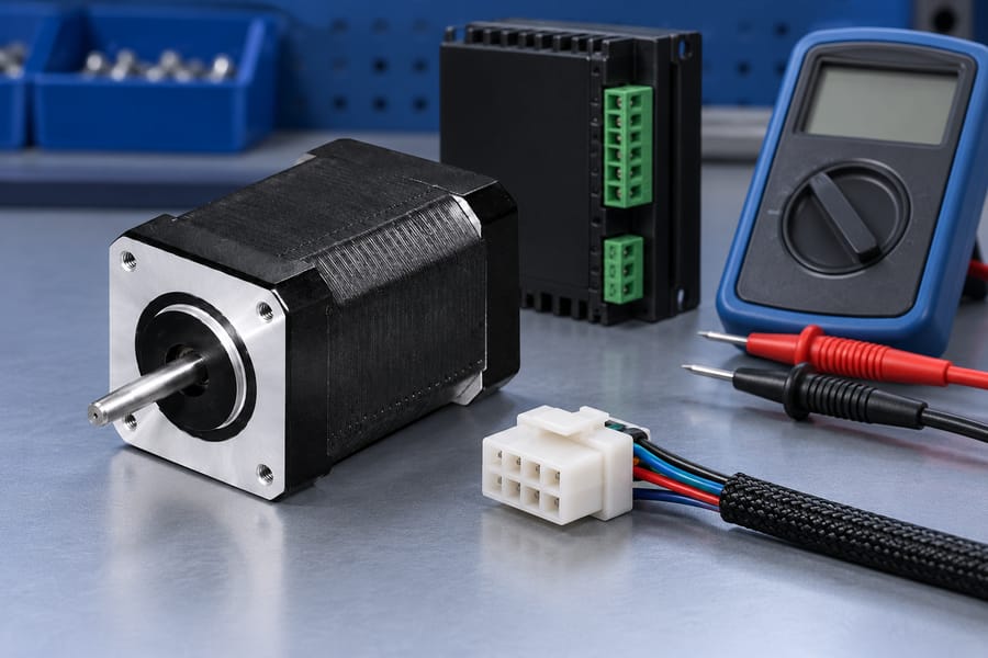
Identify the winding leads from the candidate’s wiring diagram rather than assuming that wire colors, connector shapes, or pin positions match the original motor. A mechanically compatible plug can still have an electrically incompatible pinout.
Confirm the specified winding connections and phase sequence before applying power. Where documentation is incomplete, request clarification from the supplier instead of experimenting with connections on an energized system.
Resistance and inductance can help distinguish winding characteristics, but measurements must be interpreted against the correct specification and measurement method.
Resistance readings alone cannot establish the correct phase sequence or prove that a winding is suitable for the driver.
Inspect the harness for conductor capacity, connector contact ratings, insulation condition, grounding arrangements where applicable, and routing near moving components.
A replacement that requires a new connector or cable should be evaluated as an electrical integration change, not simply a motor substitution.
Record the final pinout and wiring arrangement in the machine documentation. This gives commissioning personnel a reliable reference for troubleshooting, maintenance, and future motor replacements.
Assess Torque Across the Required Speed Range
Use the motor’s torque-speed data to confirm that sufficient torque remains available during normal operation and acceleration.
Stepper motors have speed-dependent torque characteristics, and the usable output depends on the motor, driver, supply, current setting, and operating conditions.
Compare the candidate’s torque-speed data against the existing motor under equivalent conditions. Where curves are available, check the specified driver assumptions, supply voltage, winding current, and drive mode before drawing conclusions.
Pay particular attention to acceleration and deceleration.
The motor must provide sufficient torque to overcome the driven load and accelerate its reflected inertia without losing synchronism.
A candidate with adequate steady-state torque may still fail during rapid speed changes.
Supply voltage also matters because winding inductance limits how quickly current can rise as electrical excitation changes. A suitable driver and supply may therefore be necessary to obtain the required torque at higher speeds.
If the proposed configuration cannot meet the required operating envelope with documented electrical ratings, resolve the discrepancy before mechanical installation.
The next stage of verification should proceed only after the drive arrangement and expected dynamic performance are technically credible.
Recalculate Pulse Commands and Positioning
Changing the motor phase configuration can change the relationship between controller pulses and mechanical movement. Recalculate this relationship using the selected motor’s step angle and the actual driver configuration.
Step Angle and Pulse Scaling
The step angle describes the nominal angular movement associated with one full step. The resulting movement per controller pulse also depends on the drive’s subdivision settings and command interpretation.
Do not assume that a three-phase replacement preserves the original pulse-to-position relationship. Verify the selected motor’s documented step angle, supported excitation mode, and driver settings before changing motion-control parameters.
Calculate the required pulse count from the commanded angular movement, then extend the calculation through any gearbox, belt, screw, or other transmission. This reveals whether existing positioning commands remain valid.
For a direct-drive axis, the basic relationship is:
- Full steps per revolution: 360 degrees / full-step angle in degrees.
- Command pulses per revolution: full steps per revolution × configured pulses per full step.
- Angular movement per pulse: 360 degrees / command pulses per revolution.
These equations assume the controller sends one pulse per configured drive increment. Confirm that the driver does not interpret commands differently through internal interpolation or another operating mode.
A controller may preserve its original travel commands only if the new motor and drive configuration produce the same effective movement per pulse. Otherwise, revise scaling and validate travel over the full axis range.
Hypothetical pulse-rate example — illustrative values, not product specifications
Assume a candidate has a 0.9-degree full-step angle, the selected drive uses 10 pulses per full step, and the axis must rotate at 600 rpm.
- Full steps per revolution = 360 degrees / 0.9 degrees = 400 steps.
- Command pulses per revolution = 400 steps × 10 pulses per step = 4,000 pulses.
- Rotational speed = 600 rpm / 60 = 10 revolutions per second.
- Required pulse frequency = 4,000 pulses/revolution × 10 revolutions/second = 40,000 pulses/second, or 40 kHz.
This calculation establishes the required command rate under the stated assumptions. It does not prove that the selected motor, driver, or controller can achieve the associated speed and load torque.
Controller Pulse Bandwidth
Check the controller’s maximum pulse output frequency against the calculated requirement. Also verify minimum pulse width, minimum low time, direction-signal setup and hold times, and any restrictions imposed by the selected control interface.
A controller may generate the correct total pulse count while failing to deliver pulses quickly enough at the required speed.
The result can be reduced motion speed, command errors, or an axis that cannot follow its intended trajectory.
Review how the controller generates pulses. Hardware pulse outputs, communication-based commands, and software-timed signals can have different timing constraints, particularly when several axes operate simultaneously.
Confirm that the controller and driver interpret pulse and direction signals consistently. Check active signal edges, polarity, electrical levels, and direction changes near acceleration or reversal points.
If the controller cannot meet the required bandwidth, consider a supported hardware pulse output or revised motion profile before approving the motor change.
Validate the resulting trajectory rather than assuming that a higher configured speed produces higher mechanical speed.
Check Mechanical Fit and Dynamic Response
Shaft, Flange, and Mounting
A replacement motor must fit the machine without introducing unacceptable misalignment, unsupported loads, or changes to the transmission. Compare dimensioned drawings for both motors rather than relying on nominal frame size.
Review the shaft diameter, usable shaft length, keyway or flat where applicable, coupling interface, flange dimensions, mounting-hole pattern, pilot diameter, and overall motor length. Also check connector clearance and access for installation and maintenance.
The broader stepper motor range provides product-category context, but final fit must be established from the selected motor’s specific drawing and documentation.
Check whether the existing coupling can accommodate the candidate shaft without excessive clearance or forced assembly. A coupling that appears to fit may still introduce runout, angular misalignment, or unwanted radial loading.
Verify the permitted shaft loads against the application. Belt tension, gear forces, screw thrust, and overhung components can impose radial or axial loads that the motor bearings may not support.
If an adapter plate is required, assess its stiffness, fastener engagement, alignment features, and effect on the assembly envelope.
A new mounting arrangement must preserve alignment through the operating cycle, not merely allow the motor to be installed.
Inertia and Resonance
Mechanical compatibility also depends on how the replacement responds to the driven load. Compare rotor inertia and the reflected inertia of the complete mechanism, including couplings, gears, pulleys, screws, and moving components.
Reflected inertia depends on the transmission ratio and the mechanical arrangement. Recalculate it when the replacement changes the gearbox, transmission ratio, or rotating components rather than comparing rotor inertia alone.
Assess acceleration and deceleration against the available dynamic torque. The motor must accelerate the combined inertia while also overcoming friction and external forces; insufficient margin can cause following errors or loss of synchronism.
Resonance behavior may also change because the motor, coupling, transmission, and load form a dynamic system.
Do not assume that changing phase count will eliminate vibration or that a different motor will retain the same stable speed range.
Test representative operating speeds, particularly where vibration, audible noise, or positioning errors have previously appeared.
Observe the complete mechanism, since a resonance may originate in the coupling, mounting structure, belt, screw, or load rather than the motor alone.
Where necessary, evaluate changes to acceleration ramps, operating speed, coupling stiffness, or mounting rigidity. Record any revised limits in the motion profile so that the replacement does not depend on undocumented operating restrictions.
Before proceeding to final qualification, confirm that the proposed assembly meets the machine’s dimensional requirements and can achieve the required motion under its actual load.
Any unresolved interference, excessive shaft loading, or unstable operating region should be addressed before thermal testing and acceptance.
Validate Thermal and Motion Performance
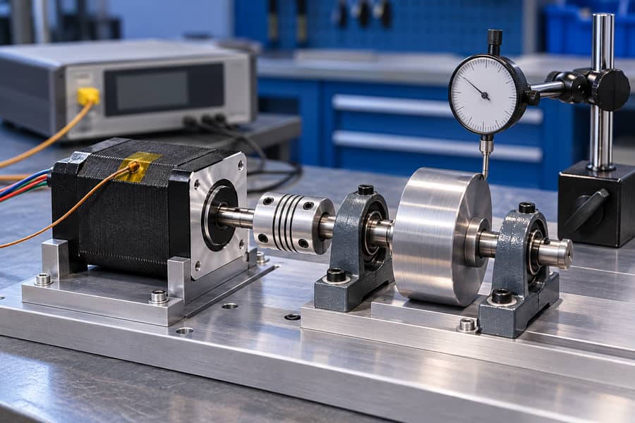
Electrical compatibility and mechanical fit establish whether the replacement can be integrated, but commissioning must demonstrate stable operation under representative machine conditions. Test the complete axis rather than evaluating the motor independently.
Test Cold and Hot Positioning Repeatability
Begin with a cold-start test after the assembly has reached a documented, repeatable starting condition. Record commanded positions, measured positions, repeatability, and any missed steps throughout representative movements.
Repeat the same measurements after the motor and drive reach thermal equilibrium under the intended operating duty. Temperature-dependent changes in the motor, coupling, mounting structure, or transmission may affect positioning and settling.
Use consistent measurement equipment, reference points, travel distances, and motion profiles. Define acceptable repeatability from the machine requirements rather than assuming the replacement should match an arbitrary universal tolerance.
Check both repeated approaches to the same position and movements in opposite directions. This helps distinguish repeatability problems from backlash, directional differences, mounting movement, and other mechanical effects.
Evaluate Settling and Resonance
Measure settling behavior after representative moves, including movements that finish near previously observed vibration regions. The axis should enter the required positioning tolerance within the machine’s specified settling time.
Test the intended speed range, acceleration settings, and direction changes. Watch for vibration, audible noise, unstable movement, position deviation, or loss of synchronism under realistic loads.
If instability appears, identify its operating conditions before changing several parameters simultaneously. Adjusting speed, acceleration, or mechanical stiffness may improve behavior, but each change requires another documented test.
Verify Real Load and Duty Cycle
Run the replacement with representative production loads and the intended duty cycle. Include the actual transmission, normal acceleration profile, dwell periods, repeated starts, and expected variations in mechanical resistance.
A brief unloaded demonstration cannot establish suitability for sustained production. Testing must cover the conditions that produce the greatest documented electrical, thermal, and mechanical demands.
Measure motor and driver temperatures using an appropriate method and at identified measurement locations. Compare the results with applicable manufacturer limits, accounting for the specified ambient conditions and cooling arrangement.
Do not substitute a generic temperature threshold for the motor’s insulation, winding, or other documented limits. Where specifications define different limits for different components or measurement methods, evaluate each against its corresponding requirement.
Record winding or phase-current measurements using equipment and methods appropriate to the drive waveform. State whether reported current is RMS or peak, where it was measured, and which operating condition produced the reading.
Check Fault Recovery and Restart Behavior
Exercise relevant faults and recovery procedures under controlled commissioning conditions. Verify that the drive responds appropriately to overtemperature warnings, loss of control signals, supply interruptions, and other faults supported by the installed system.
After a fault clears, confirm that restart behavior follows the machine’s control and safety requirements. Check homing, position-reference validity, retained commands, and recovery from interrupted movement before permitting automatic operation.
Set Pass/Fail Criteria and Recovery Triggers
Document the required test limits and the circumstances that would require restoring the previously validated configuration before commissioning starts.
Define the required performance, measurement method, operating conditions, and permitted tolerances so that approval does not depend on subjective impressions.
The following table provides a practical framework. Insert the machine’s actual requirements and the applicable documented limits before execution; none of these criteria should be treated as a universal numerical specification.
| Test item | Verification method | Acceptance evidence |
| Positioning repeatability | Compare repeated cold and hot moves | Results meet the specified positioning tolerance |
| Settling and resonance | Test representative speeds and transitions | Settling time and vibration meet machine requirements |
| Load and duty | Run representative loads through the intended cycle | No unacceptable lost steps, overheating, or performance degradation |
| Electrical current | Measure using a documented method and RMS/peak convention | Current remains within applicable motor and driver limits |
| Thermal behavior | Record temperatures at identified locations | All readings comply with documented component limits |
| Fault and restart | Simulate applicable faults and recovery sequences | Recovery follows control, reference, and safety requirements |
| Mechanical integrity | Inspect mounting, coupling, shaft loading, and fasteners | No unacceptable movement, interference, or mechanical damage |
Establish Approval and Rollback Rules
Approve the replacement only when every critical acceptance requirement passes under the agreed test conditions. Document any permitted deviation explicitly and obtain the responsible engineering approval before releasing the machine for production.
A failed critical test should prevent unrestricted deployment. Examples include exceeding documented thermal limits, losing synchronism under the required load, failing positioning tolerances, or exhibiting unacceptable resonance within the required operating range.
Retain the original motor and its tested configuration until the replacement completes acceptance.
Preserve the original driver settings, wiring diagram, controller parameters, mechanical arrangement, and known-good motion profile so the machine can return to a verified state.
If rollback becomes necessary, isolate the machine according to its established procedures, restore the original configuration, and verify the affected axis before resuming production.
Do not assume that reinstalling the original motor automatically restores previous performance after wiring or control changes.
When a test fails, record the operating conditions and measured result before modifying the system.
Corrective actions should identify the cause, specify the change, and repeat the affected tests, including regression checks for previously passed requirements.
Prepare the Supplier Approval Package
The final approval package should contain the selected motor’s exact model and specification revision, dimensioned drawing, winding diagram, electrical ratings, and applicable torque-speed data.
Include the driver model, current-setting method, RMS/peak convention, supply conditions, and controller pulse settings.
Attach the measured cold and hot positioning results, settling and resonance observations, actual-load duty-cycle logs, temperature records with measurement locations, and fault-recovery results.
Include acceptance criteria, deviations, corrective actions, final controller parameters, and the rollback configuration identifier.
Supplier approval should reference these specific records, the completed acceptance results, and the authorized final configuration revision, allowing the engineering team to reproduce the test conditions and trace the approved replacement to its documented evidence.