
Choosing between direct coupling and a belt drive starts with the axis mechanics, not a blanket claim about accuracy or compactness.
The right arrangement depends on motor placement, load path, travel, speed, stiffness, service access, and the positioning tolerance the machine must achieve during the full duty cycle across repeated production cycles.
Identify the Three Axis Configurations
Direct-Coupled Stepper Motor and Lead Screw
In a direct-coupled axis, the motor shaft connects to the screw through a flexible or rigid coupling. Motor rotation turns the screw without a belt stage, so both shafts generally share an axis.
Before choosing the coupling, check the selected stepper motor for shaft geometry, torque capacity, speed range, mounting constraints, and clearances.
This arrangement avoids belt tensioning and pulley-ratio choices, but alignment remains essential. Misalignment can create coupling forces, vibration, heat, or bearing loads beyond what the coupling can accommodate.
Confirm shaft diameters, usable shaft length, and any required flats or keyways before specifying the coupling. The motor should not become an unintended thrust bearing for the screw.
Belt-Driven Lead Screw
A belt-driven screw places the motor away from the screw and transfers rotation through a timing belt and pulleys. This offset layout can free space around the screw.
The belt stage adds components and setup variables. Pulley sizes set the ratio, while belt tension, span length, tooth engagement, and support stiffness influence load transfer and motion response.
Allow a way to adjust center distance or tensioner position during assembly. Excessive tension raises shaft and bearing loads; insufficient tension risks tooth jumping or speed variation under changing load.
Belt-Driven Linear Axis
A belt-driven linear axis uses the belt itself to move the carriage along a rail, rather than rotating a lead screw. It may suit layouts prioritizing long travel or linear speed.
Do not treat it as a belt-driven screw with a different motor position. Its belt stretch, carriage guidance, pulley geometry, and force path differ from a screw’s lead, nut, and support behavior.
Here, pulley tooth pitch and belt width must suit carriage force and duty cycle. The rail guides the carriage, while belt stiffness and anchoring influence its motion response.
| Configuration | Motion conversion | Main layout consideration |
| Direct-coupled screw | Motor rotation turns the screw | Motor and screw share an axis |
| Belt-driven screw | Belt turns a separate screw | Motor can sit offset from the screw |
| Belt linear axis | Belt directly moves the carriage | Belt path and rail define the travel envelope |
Compare Layout, Loads, and Motion Performance
Axial Space, Offset Placement, and Packaging
Direct coupling removes the belt-and-pulley stage, but it does not automatically make a machine the shortest or narrowest. The motor adds length along the screw axis, and the coupling needs service clearance.
Offset mounting can use space beside, above, or below the screw, reducing axial length while increasing width or height. Compare the complete envelope, including cables, guards, tensioners, end supports, and tool access.
Leave enough room to remove a coupling or belt without dismantling adjacent modules. A compact-looking drive can create a costly service problem when guards or frame members block access.
For a belt linear axis, map the belt loop and full carriage stroke. Check return spans, idlers, end pulleys, and tensioning hardware against covers, sensors, and neighboring motion.
Coupling Alignment, Shaft Support, and Bearing Loads
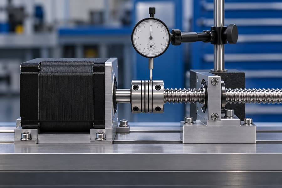
Align the motor shaft and screw input within the coupling manufacturer’s limits. A flexible coupling accommodates only specified misalignment; it cannot correct poor mounting geometry or an unsupported screw.
Check motor and screw supports separately. Screw bearings must carry the loads specified for the screw assembly; do not assume motor bearings can take axial thrust or external radial forces unless documentation permits.
During assembly, check shaft and screw runout, mounting-face squareness, and free rotation before tightening the coupling. Binding or periodic resistance can indicate alignment or support problems.
Alignment reduces unwanted forces but does not guarantee positioning accuracy. Screw lead error, coupling torsional stiffness, backlash, thermal growth, and frame deflection also influence carriage position.
Timing-Belt Reduction Ratio, Pulley Diameter, and Output Speed
Define timing-belt reduction ratio as motor speed divided by output speed. A 2:1 ratio means the motor turns twice per output revolution; output speed halves, while ideal output torque rises about twofold before losses.
For a simple timing-belt stage, ratio equals driven-pulley tooth count divided by driving-pulley tooth count. A 60-tooth driven pulley and 30-tooth driver therefore provide 2:1 reduction.
Identify which pulley sits on the motor to prevent ambiguity. Pulley diameter also affects packaging, belt wrap, tooth engagement, and belt bending; check minimum-diameter guidance from the belt supplier.
For a screw axis, nominal linear speed equals screw rpm multiplied by screw lead. With reduction, screw rpm equals motor rpm divided by the ratio; verify units and commanded speed before sizing the motor.
Combine the ratio with screw lead to estimate travel per motor revolution. With a 5 mm screw lead and 2:1 reduction, one motor revolution advances the screw half a turn, or 2.5 mm nominally.
Pulley Overhang, Radial Loads, and Bearing Support
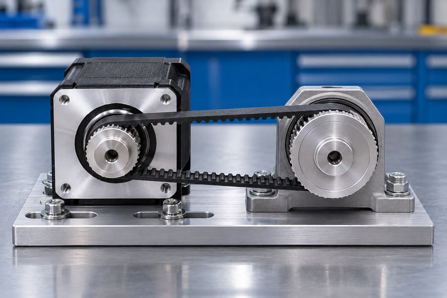
A timing belt loads its pulleys radially because the tight and slack spans both pull on the pulley. The resulting shaft force depends on belt tension, transmitted torque, and span direction—not torque alone.
Mounting a pulley beyond the motor’s front bearing creates an overhung load.
The farther the pulley sits from the bearing, the greater the bending moment for the same radial force, potentially increasing shaft deflection and bearing stress.
Check the motor documentation for permissible radial load and the distance from the bearing reference point at which that limit applies.
Do not assume a shaft can support a larger pulley simply because its bore fits.
If the required belt force exceeds the motor’s allowable load, use a separately supported jackshaft or pulley shaft with suitable bearings. The motor then transmits torque without carrying the full belt load directly.
Support the screw independently according to its axial and radial load requirements. In a belt-driven linear axis, support end pulleys and idlers in a rigid frame; frame flex can alter belt tracking and carriage position.
Belt Tension, Compliance, and Positioning Stability
Set belt tension using the belt manufacturer’s specified method, such as a prescribed deflection force or frequency. Avoid tightening by feel alone, because excess pretension adds bearing load without necessarily improving positioning.
Insufficient tension can allow poor tooth engagement, vibration, or tooth skipping during acceleration and reversal. Excessive tension can shorten bearing life, increase shaft deflection, and raise friction in the transmission.
A timing belt is compliant, so transmitted force stretches the belt and deforms its teeth. Under changing load, this elasticity can produce small position deviations even when the belt does not visibly slip.
Other contributors include pulley eccentricity, tooth clearance, loose hubs, flexible mounting plates, and carriage or screw support movement. Inspect the complete force path instead of attributing every repeatability problem to the belt itself.
Use belt width, tooth pitch, pulley tooth count, span length, and belt construction appropriate to the required force and speed.
A longer free span generally has more compliance than a shorter span of the same belt type and section.
For axes that reverse frequently, evaluate bidirectional repeatability and settling after direction changes. Tension must remain stable through the operating range, and the tensioning arrangement should remain accessible for inspection and service.
Reflected Inertia, Acceleration, Resolution, and Accuracy
Acceleration depends on the inertia the motor must accelerate, the load torque, friction, and the torque available at the commanded speed.
A transmission ratio changes both output speed and the load inertia reflected to the motor.
For a reduction ratio i defined as motor speed divided by output speed, output-side rotational inertia reflected to the motor is:
Jref = Joutput / i²
This ideal relationship assumes a rigid ratio and excludes losses and compliance.
Do not combine every inertia term as though it were on the same shaft.
Motor rotor inertia and the motor-mounted pulley inertia act directly at the motor; output pulley, screw, and mechanism inertia must be reflected through the ratio before summing.
Hypothetical ratio/inertia example: A 2:1 belt reduction drives a mechanism with 8,000 g·cm² of output-side inertia. Its reflected value is:
8,000 / 2² = 2,000 g·cm² at the motor.
Assume the motor rotor inertia is 200 g·cm², the motor pulley is 40 g·cm², and the driven pulley is 100 g·cm². The driven pulley’s reflected contribution is:
100 / 4 = 25 g·cm².
The approximate motor-side total is therefore:
2,000 + 200 + 40 + 25 = 2,265 g·cm²
This estimate excludes other inertia terms and transmission losses. The reflected mechanism inertia alone is ten times the assumed rotor inertia.
Treat this calculation as an example; the acceptable inertia balance depends on the specific axis and its operating demands.
Acceptability depends on the motor’s torque-speed curve, acceleration profile, resonance behavior, friction, load variation, and the drive’s operating limits.
A larger reduction may reduce reflected output inertia and increase available output torque, but it also reduces output speed for a given motor speed.
Confirm the resulting cycle time rather than choosing a ratio from inertia alone.
When evaluating a hybrid stepper motor, compare available torque at the required operating speed, not just holding torque. Include the actual supply, driver, current setting, and acceleration profile in the assessment.
Finally, distinguish command resolution from positioning accuracy. Microstepping can provide finer command increments, but actual position also depends on load, torque margin, friction, mechanical compliance, screw lead error, and repeatable homing or feedback where used.
Test the axis with representative loads and reversals. Record commanded and measured travel, repeatability, settling time, and missed-step symptoms; a high nominal pulse count does not prove that the mechanism reaches each commanded position.
Select and Verify the Appropriate Configuration
Match Transmission Architecture to Load and Travel Requirements
Start with the required travel, moving mass, external forces, cycle time, and positioning behavior. These requirements determine whether the axis needs screw-driven motion or direct belt-to-carriage transmission.
For a direct-coupled screw, check whether the motor, coupling, screw, and end supports fit within the available axial envelope. This arrangement removes the belt stage but can make the complete axis relatively long.
A belt-driven screw separates motor placement from the screw axis. This helps when frame geometry restricts inline mounting, provided the design accommodates pulleys, belt spans, tension adjustment, and adequate shaft support.
A belt-driven linear axis is worth evaluating when the machine needs longer travel or higher linear speed. Its suitability depends on belt stiffness, carriage force, rail guidance, and the required positioning behavior.
Compare travel and speed using the actual transmission geometry. Screw speed multiplied by screw lead determines nominal linear speed, while belt travel per pulley revolution depends on pulley tooth pitch and tooth count.
Neither architecture guarantees better accuracy. Screw lead error, belt elasticity, mounting stiffness, backlash, thermal effects, motor torque margin, and control settings influence the result in different proportions.
For each candidate, calculate required motor speed and torque throughout the motion profile. Include acceleration, deceleration, gravity loads where applicable, friction, and any external process force instead of evaluating steady motion alone.
Compare the required torque with the motor’s available output at the intended running speed. A theoretically suitable ratio may still fail if acceleration demand exceeds available torque or the resulting cycle time is unacceptable.
Evaluate Accessibility, Adjustment, and Lifecycle Cost
Review how technicians will assemble, inspect, adjust, and replace the transmission. Direct coupling requires alignment checks and coupling access, while belt systems need additional clearance around pulleys, spans, and tensioning hardware.
Direct coupling may reduce component count, but difficult axial access can increase disassembly time. Offset belts may simplify motor removal while requiring more frame space and periodic tension inspections.
Include the cost of couplings, belts, pulleys, supports, tensioners, guards, machining, and assembly labor. Compare complete installed arrangements rather than comparing the purchase price of individual transmission components.
Assess how transmission wear or a component failure could interrupt production and complicate repairs. Replacement time, spare-part availability, alignment or retensioning procedures, and the need to remove neighboring assemblies can influence lifecycle cost.
For production equipment, standardize inspection points and service procedures where practical. Provide access to coupling fasteners, pulley hubs, bearing supports, and belt tension measurements without compromising guarding or other safety requirements.
Before releasing the mechanical design, verify the transmission envelope against the actual frame and neighboring equipment. Include cable routing, sensor positions, lubrication access, and the space needed for tools during maintenance.
Define Measurable Acceptance Tests
Acceptance criteria should come from the machine’s functional requirements, approved drawings, component documentation, and intended duty cycle. Do not substitute generic tolerances for limits that must reflect the actual application.
Test the completed assembly after alignment, fastening, lubrication where required, and belt tension adjustment. Begin with controlled low-speed movement, then progress to representative operating speeds and loads.
Measure actual carriage travel against commanded travel at multiple positions. For screw axes, consider lead-related variation; for belt axes, check whether compliance, pulley geometry, or mounting movement affects the result.
Repeat measurements in both directions and after reversals. Measure repeatability independently of absolute positioning error, since an axis may return reliably to the same location while consistently missing its commanded target.
Test the intended acceleration and deceleration profile under representative loading. Record settling behavior, vibration, motor temperature, and any evidence of missed steps or unstable motion during repeated cycles.
| Test condition | Measurement | Machine-specific pass criterion |
| Assembly and alignment | Shaft alignment, runout, free rotation, and support condition | Within coupling, screw, and bearing documentation limits; no unacceptable binding |
| Belt installation | Tension, tracking, tooth engagement, and pulley security | Meets belt requirements and remains stable during operation |
| Travel accuracy | Commanded versus measured position across the working stroke | Meets the approved positioning-error budget throughout the required travel |
| Bidirectional repeatability | Repeated measurements from both approach directions | Meets the application’s documented repeatability requirement |
| Dynamic operation | Acceleration, cycle time, settling, and vibration | Completes the specified motion profile without unacceptable instability or missed steps |
| Representative load and duty | Positioning results, motor temperature, and sustained operation | Meets cycle requirements and documented component operating limits |
| Maintenance access | Tool clearance and component removal procedure | Required inspection, adjustment, and replacement tasks can be completed as designed |
If the axis fails a test, isolate the cause before changing the transmission ratio or motor settings. Check mechanical alignment, support stiffness, belt tension, friction, and load assumptions before modifying control parameters.
Repeat affected tests after each corrective change, then rerun the complete operating sequence to confirm that improvements do not create new problems. Preserve the previously approved configuration so rollback remains possible.
The layout approval record should include the selected architecture, dimensioned assembly drawing, motor and transmission calculations, pulley or screw specifications, bearing-load checks, alignment and tension settings, measured acceptance results, component limits, maintenance clearances, and any approved deviations.