
Mid-speed resonance in a stepper axis reflects an interaction between rotor/load dynamics and the motor-drive system that reduces effective damping or available synchronizing torque at certain operating conditions.
It is not defined by a universal RPM range, and vibration alone does not prove resonance. The cause must be identified before changing current, drive settings, transmission stiffness, or load inertia.
What Causes True Mid-Speed Electromechanical Instability?
A stepper axis can become unstable when electromagnetic torque, rotor motion, and the attached load interact in a way that sustains or amplifies oscillation.
The key distinction is between a system that develops oscillation through its own coupled dynamics and one that merely vibrates because an external force excites a mechanical structure.
Motor and Load Inertia Interaction
Couplings, pulleys, screws, gears, and the driven mechanism contribute inertia reflected to the motor shaft, while compliance and backlash can add further dynamic effects.
The combined inertia affects how quickly the rotor responds to changing torque and how the axis reacts to disturbances during commanded motion.
A heavier load may shift natural frequencies, increase acceleration demand, or make an existing oscillation harder to control; the outcome depends on the transmission and operating point.
Inertia is not automatically harmful, and adding it is not a reliable cure; the effect depends on the axis dynamics and operating point.
A flywheel or heavier coupling may shift a response peak, but it can also increase torque demand and reduce acceleration margin, so evaluate the complete axis.
Electrical Damping, Phase Lag, and Drive Dynamics
A stepper motor’s electromagnetic torque depends on how commanded phase currents align with rotor position and motion at the operating speed.
The drive regulates winding current, but electrical time constants and the motor’s changing back electromotive force affect how current follows its reference as speed rises.
Damping depends partly on the phase relationship between rotor oscillation and the electromagnetic torque generated in response to it during motion.
A torque component that opposes motion can dissipate oscillation energy; if response lag shifts that component, it may provide less damping or reinforce the motion instead.
This relationship varies with motor construction, drive control, current settings, supply voltage, and the actual operating speed of the axis.
Mid-speed instability cannot be attributed to phase lag alone, nor does every drive produce the same unstable region under all conditions.
The practical question is whether the combined motor-drive response leaves sufficient damping and synchronizing torque at the observed operating point.
An overly low current setting, incorrect drive configuration, supply limitations, or a genuine drive fault can also cause rough running or lost steps.
Treat these as differential diagnoses, not defining causes of true mid-speed electromechanical instability unless measurements support that classification in the tested axis.
A useful starting point is to review the operating torque requirement against the selected stepper motor’s torque-speed behavior, rather than judging suitability from holding torque alone.
Distinguishing Low-Speed Resonance from Mid-Speed Instability
Low-speed resonance commonly involves rotor and load oscillation excited by the motor’s stepping action, particularly where the mechanical system has limited damping.
It may appear as pronounced vibration, audible noise, or uneven motion during a repeatable portion of the speed sweep under similar loads.
Mid-speed instability is more closely associated with the coupled motor-drive-mechanical response as electrical and mechanical conditions change with speed under actual operating conditions.
It may emerge after an axis accelerates beyond a lower-speed region, but its location is system-specific and should be measured rather than assumed.
Labels alone cannot identify the mechanism, because low- and mid-speed symptoms can overlap in a real axis under load during testing.
A vibration at higher speed may instead come from a loose component, periodic load disturbance, or inadequate torque margin within the mechanism.
Separating Electromechanical Instability from Mechanical Forced Resonance
Mechanical forced resonance occurs when a repeating external excitation approaches a structure’s natural frequency and produces a larger vibration response.
Potential sources include cyclic process forces, gear or belt excitation, screw-related periodic effects, or an unbalanced rotating component during normal operation.
In this case, the excitation originates outside the motor’s electromechanical feedback behavior, even though the stepper axis may transmit or amplify it.
The vibration may track a machine cycle, rotation rate, or process event rather than appearing solely because the motor-drive system becomes unstable.
Loose mounts, coupling damage, bearing problems, backlash, or structural flexibility can also cause vibration without a true resonant condition in the axis.
Inspect these possibilities before assigning the symptom to resonance; confirm a speed-related pattern and repeatability on the actual machine before changing control parameters.
| Observed pattern | Possible explanation | Useful distinction |
| Oscillation concentrated at low speed | Step-related rotor/load resonance | Check whether it changes with low-speed operating conditions |
| Oscillation appears in a repeatable mid-speed region | Motor-drive electromechanical instability | Compare controlled speed sweeps and load conditions |
| Vibration follows a process cycle or rotating component | Mechanical forced excitation | Check whether the excitation tracks the external cycle |
| Rough motion occurs across varied speeds or after a fault | Loose mechanics, torque shortage, current/configuration issue, or drive fault | Inspect hardware and verify drive settings before classifying it as resonance |
How to Diagnose Mid-Speed Resonance Systematically
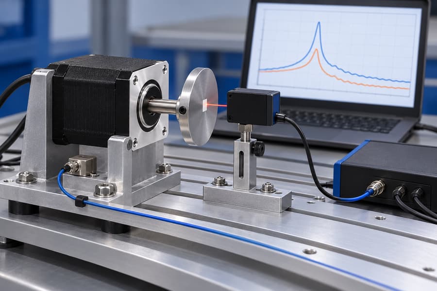
Diagnosis should begin with a repeatable operating pattern, not an immediate adjustment to the drive. The aim is to identify when oscillation begins and which conditions change it.
Run Controlled Speed Sweeps Under Representative Loads
Use the same commanded speed range, acceleration profile, travel direction, payload, transmission setup, and measurement locations for each comparison. Record the settings before changing anything.
Sweep upward through the suspected region in small, repeatable speed increments, then sweep downward through the same range. A recurring peak helps locate the operating condition, but does not prove its mechanism.
Compare slow and fast ramps while keeping the speed range and load consistent. A slow sweep can reveal narrow response regions, while a fast ramp may pass through before oscillation develops.
Ramp rate also changes acceleration torque demand and the time spent near a response peak. If results differ, repeat the test and separate transient acceleration effects from sustained-speed behavior.
Test with the real load and representative machine cycle, not only an unloaded motor. Load inertia, friction, belt tension, screw forces, and process contact can change the axis response substantially.
Keep winding-current settings, supply voltage, driver mode, payload, and initial thermal state consistent between trials. Allow the motor and drive to return to a comparable temperature before comparing results.
Record Vibration, Noise, Position Errors, and Missed Steps
Use available measurements that can be repeated: an accelerometer, displacement probe, encoder feedback, controller position-error logs, or synchronized video. Record the measurement location and sampling conditions.
Sound can help identify a repeatable symptom, but listening alone cannot distinguish resonance from rubbing, looseness, or missed steps. Pair acoustic observations with vibration or motion measurements whenever possible.
Check commanded and actual position where feedback is available, and inspect reference marks or independent displacement measurements where it is not. A growing position offset may indicate lost synchronism rather than vibration alone.
A stepper can lose steps because available torque falls below demand, current is configured incorrectly, supply voltage is inadequate, or the drive faults. These conditions need separate checks before assigning the event to resonance.
Review alarms, fault history, current configuration, supply behavior, acceleration settings, and mechanical drag. If the axis stalls across a broad speed range or under sudden load changes, investigate torque margin and faults first.
Stop testing if oscillation grows rapidly, the rotor loses synchronism, the mechanism strikes a limit, or temperature exceeds documented limits. Secure the machine before inspection; do not continue merely to map the failure.
How to Reduce Mid-Speed Resonance
Evaluate Drive Anti-Resonance Functions and Current Settings
First establish a baseline with the approved motor-drive configuration and record every relevant parameter. Consult the drive documentation to understand what each anti-resonance or damping function changes.
Where a suitable function exists, test it using the same controlled sweep and representative load. Change one parameter at a time, then compare vibration, position behavior, noise, and usable speed range.
Confirm that phase current is set according to the drive’s stated convention, such as peak or RMS, and the motor’s permitted rating. A mismatched interpretation can produce too little torque or excessive heating.
Also verify supply voltage at the drive under motion, wiring integrity, connector condition, and any current-reduction feature active at speed. Correct an identified configuration or hardware fault before tuning around its symptoms.
Anti-resonance functions may improve stability within a particular operating region, but they are not interchangeable across drives and cannot correct every mechanical excitation. Keep the original settings available for rollback.
If changing a setting moves the vibration peak rather than reducing its severity, assess the complete operating range before accepting the adjustment.
A drive adjustment that reduces oscillation at one speed may increase vibration or compromise stability elsewhere in the operating range.
Understand Microstepping Benefits and Limitations
Microstepping divides each full motor step into smaller commanded current-vector increments. It can reduce step-to-step excitation and improve low-speed smoothness, depending on motor, drive, load, and operating conditions.
However, finer command increments do not guarantee equivalent mechanical position increments under load. Incremental torque, friction, compliance, and disturbances can prevent the rotor from following each microstep precisely.
Microstepping may reduce one source of excitation, but it does not guarantee removal of mid-speed instability caused by coupled electromechanical dynamics or externally forced vibration.
When changing microstep resolution, verify controller pulse frequency, available high-speed pulse output, command scaling, and acceleration settings. Higher resolution may require more input pulses for the same axis speed.
Keep the motor-drive combination and actual load in the test. A hybrid stepper motor still needs evaluation against drive behavior, required torque, and axis operating conditions; microstep resolution alone cannot establish suitability.
Compare results over the full required speed range, including acceleration and deceleration, rather than judging success from quieter motion at one point. Record whether the change reduces measured oscillation without worsening position behavior.
Assess Mounting, Couplings, Rigidity, and Mechanical Damping
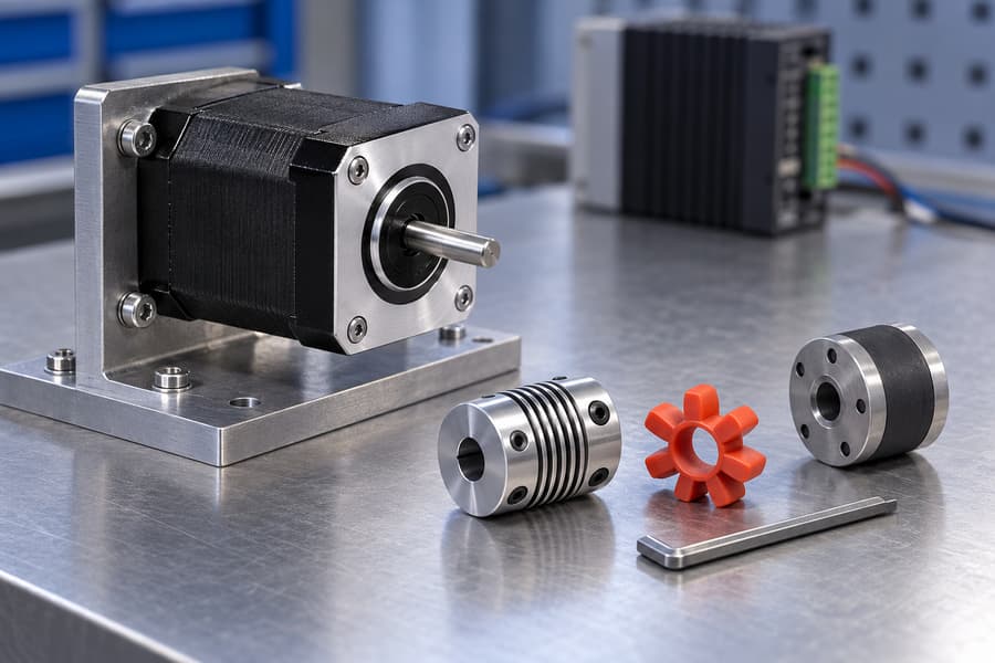
Inspect the mechanical path before replacing components. Check mounting bolts, base contact, bearing supports, coupling alignment, belt condition, screw supports, and signs of wear or looseness.
A loose joint can create impact, backlash, or intermittent motion that resembles resonance. Correct verified defects first, then repeat the same speed sweep to determine whether the original pattern remains.
Structural flexibility may amplify vibration when an excitation overlaps a frame, bracket, or transmission mode. Measure at more than one location when possible to distinguish motor-side motion from a flexible downstream structure.
Increasing stiffness is not automatically beneficial. It can shift a natural frequency into another operating region, alter force transmission, or move vibration into a component that was previously less responsive.
Likewise, do not add damping material or change coupling type without checking load capacity, alignment, temperature, torsional compliance, and manufacturer limits. A change that reduces one vibration peak may worsen positioning or introduce another mode.
Use the measured response to target the relevant part of the assembly. If vibration is strongest at a support or bracket, evaluate that structure.
If vibration tracks a periodic process force, investigate the excitation source rather than treating the motor as the sole cause before making motor-side changes.
Evaluate Load Inertia and Transmission Tradeoffs
Estimate the inertia reflected to the motor through the actual transmission, including rotating components and the driven mechanism. Account separately for motor-rotor inertia and the inertia of pulleys, couplings, gears, screws, and loads.
Reducing moving mass or rotating inertia can lower acceleration demand, but may not remove a resonance governed mainly by compliance, damping, or external excitation. Confirm the dominant mechanism before redesigning the load.
Adding a flywheel or heavier component may shift a response peak, yet it also raises torque demand during acceleration and deceleration. Consider the complete duty cycle rather than optimizing one steady speed.
Transmission ratio changes can alter reflected inertia, available output torque, motor speed, and the relationship between motor rotation and linear travel.
Check whether the new ratio moves the problem outside required operating conditions without creating a different limitation or reducing required acceleration margin.
Belt, screw, and geared arrangements have different compliance, friction, backlash, and speed characteristics. Compare the assembled system under representative loads; no transmission type or inertia ratio guarantees stability in every application.
How to Validate the Corrective Changes
Validate the revised configuration over the machine’s actual operating envelope. Include required speed bands, acceleration and deceleration, direction reversals, dwell periods, representative payloads, and process forces.
Repeat both upward and downward sweeps, then test steady operation at relevant speeds. A correction should reduce the measured symptom without simply moving it to another required operating point.
Check cold-start behavior and repeat tests after the motor, drive, and mechanism reach their normal operating temperatures. Temperature changes can affect winding resistance, current behavior, lubrication, clearances, and mechanical response.
Set measurable position and settling criteria before testing. Use the available encoder, displacement measurement, or repeatable reference method to assess following error, repeatability, settling time, and any accumulated position offset.
Compare results against documented motor and drive limits for current, voltage, temperature, speed, and duty. Do not create generic RPM or temperature thresholds when equipment documentation and application requirements define the applicable boundaries.
The acceptance run should cover transient and steady-state operation with the final payload and representative process forces.
Check for missed steps, fault events, unexpected noise, excessive vibration, thermal drift, and recovery after a controlled stop and restart under representative conditions.
| Targeted change | Main tradeoff | Validation check |
| Correct mounting or coupling defects | Alignment work or downtime | Repeat sweeps and inspect vibration at the affected structure |
| Adjust damping or support design | May shift response or add compliance | Measure vibration and position behavior across required speeds |
| Reduce or redistribute inertia | May change capacity, stiffness, or cycle time | Test acceleration, deceleration, settling, and loaded motion |
| Change transmission ratio or arrangement | Alters speed, torque, backlash, and reflected inertia | Verify full travel, speed range, positioning, and duty cycle |
| Tune drive functions or current | May affect heat, torque margin, or another speed region | Compare baseline and revised settings under identical conditions |
Stop the test if vibration escalates, synchronism is lost, the axis hits a limit, abnormal heating occurs, or any documented operating limit is exceeded. Investigate the cause before resuming.
The final record should identify the motor and drive configuration, firmware or parameter set where relevant, current convention, supply conditions, transmission, and load details.
Record the test procedure, instrument locations, cold and hot results, measured acceptance values, and any stop events.
Preserve the approved settings and raw measurements so another engineer can reproduce the test and verify the same operating envelope.