
Specify backlash for a reversing geared stepper axis as output angular lost motion measured under defined test conditions, not as an unqualified precision label.
State torque endpoints, temperature, preload, and measurement method, and identify whether the limit applies to a new unit or an end-of-life condition. Separate clearance-only backlash from total measured movement and commanded-reversal positioning error.
Distinguish Backlash from Other Motion Errors
Clearance-only backlash is the angular gap associated with gear-tooth clearance when load transfers from one contacting flank to the opposite flank. It describes geometric clearance, not every movement observed during a loaded reversal.
Reported lost motion is output angular movement recorded between defined torque or motion endpoints. Depending on the method, it can include tooth clearance, elastic deformation, bearing movement, shaft twist, fixture flexibility, and other mechanical effects.
Elastic compliance is reversible deformation under torque.
Shafts, gear teeth, bearing supports, and mounting plates can deflect as torque changes, even after gear flanks contact.
This movement contributes to measured angular change but is not itself clearance.
Hysteresis describes differences in torque-angle or position response depending on loading direction and history. Friction and contact behavior can complicate identification of a clearance interval, especially across a broad torque range.
Missed steps occur when the motor fails to follow commanded motion, for example when dynamic torque demand exceeds available torque. They are not gearbox backlash, although both may appear as position error after reversal.
Step angle, microstep setting, and nominal command resolution do not establish output accuracy. Gear ratio scales motor motion, while clearance, compliance, loading, and control behavior affect how closely the output follows a changing command.
Define the Backlash Measurement Method
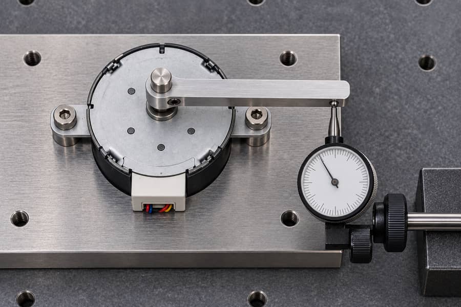
Lock the input and apply reversing output torque
A static test can restrain the motor input and apply specified positive torque to the gearbox output, then reverse to a specified negative torque.
The output is not assumed to remain motionless: it can rotate through clearance and deform elastically while the input stays locked.
Record output angle against applied torque, or measure output positions at defined positive and negative torque endpoints.
Their angular difference is the reported lost motion for that test.
State torque magnitudes and endpoint rules so results remain comparable.
Do not call endpoint-to-endpoint movement clearance-only backlash unless the method separates elastic and fixture deflection from the clearance interval. If the test reports total movement, retain that name in drawings, supplier documents, and acceptance records.
Define the mechanical and environmental reference conditions
Specify mounting, input restraint, angle-measurement location, and whether an external coupling or fixture is attached to the output. Fixture flexibility and shaft misalignment can alter results, so the arrangement must be repeatable and documented.
Record test temperature and any preload applied to the output or gear train.
Preload can reduce apparent clearance in some arrangements while increasing friction or changing contact behavior; results under different preload conditions are not directly interchangeable.
Define torque range, direction sequence, loading rate, dwell time if used, and cycles completed before recording. The goal is not one universal procedure, but a reproducible condition for every reported value.
State the reported quantity and reference side
Use output angular units, such as degrees, arcminutes, or radians, and state measurement resolution. If a value is referred to the motor input, label that reference explicitly.
Calculate the reduction ratio, i, by dividing motor speed by gearbox output speed, and use this convention consistently throughout the specification.
The input-referred angle equals output angle multiplied by i; output angle equals input-referred angle divided by i.
This conversion changes the reference coordinate, not the gearbox’s physical clearance.
| Reported quantity | Conditions to state | What it represents |
| Clearance-only backlash | Clearance-identification method; torque convention; temperature and preload | Estimated angular clearance between opposing gear-contact states, with compliance separated by a validated method |
| Output lost motion | Output torque endpoints; input restraint; temperature; preload; mounting and sensor | Measured output-angle change during reversal, potentially including elastic and fixture deflection |
| Input-referred angle | Original quantity and reduction-ratio convention | Output angle converted to the motor-side reference; not a separate physical measurement |
| Commanded reversal error | Motion profile, load, speed, acceleration, controller and measurement method | Whole-axis response, including effects beyond static gearbox clearance |
Keep static and commanded tests distinct
A static torque-reversal test measures movement under specified loading with the input restrained. A commanded reversal test drives the motor through a defined motion profile and measures axis response under operating load.
The dynamic result may include gearbox lost motion, missed steps, coupling and screw effects, structural flexibility, control timing, and measurement filtering.
Use static testing for a defined mechanical quantity, then test commanded reversal against the machine’s positioning requirement.
The product family page can support selection discussions about geared stepper configurations, but available structures and data must be confirmed for the specific motor variant.
See the geared stepper motor range without assuming every structure or rating applies across the family.
Convert Angular Lost Motion into Linear Error
Angular lost motion becomes easier to evaluate when converted into the displacement of the driven mechanism. For a screw-driven axis, the conversion depends on screw lead and the angular movement measured at the screw.
Use this formula when the gearbox output directly drives the screw, with one screw revolution corresponding to one output revolution:
Nominal linear lost travel (mm) = screw lead (mm/rev) × output angular lost motion (degrees) / 360
For example, assume a hypothetical gearbox has 30 arcmin of measured output lost motion and drives a screw with a 10 mm/rev lead. These illustrative values are not product specifications.
Convert the angular value first: 30 arcmin = 0.5 degrees. The nominal linear equivalent is 10 × 0.5 / 360 = 0.0138889 mm, or approximately 0.0139 mm.
This calculation expresses the linear equivalent of the specified angular interval. It does not establish the complete axis positioning error, nor does it prove that the gearbox contributes only this amount during actual operation.
The conversion assumes direct coupling and a one-to-one relationship between gearbox output rotation and screw rotation. If an additional belt, pulley, or transmission stage intervenes, include its motion ratio.
Reversal direction also matters. Lost travel describes movement across defined reversal endpoints, rather than automatically representing an error on each side of a nominal position. Clarify the reference positions before allocating the error budget.
For a lever or rotary linkage, the relationship depends on the geometry between angular motion and the measured linear direction.
For small angular changes, tangential displacement is approximately the effective radius multiplied by angular displacement in radians.
Use these formulas:
- Angle in radians = angle in degrees × pi / 180
- Tangential displacement = effective radius × angular displacement in radians
For a linear projection or linkage with changing geometry, the tangential formula may not describe the actual measured displacement. Use the mechanism’s kinematic relationship to calculate the relevant component.
Convert between output and input reference angles
A geared stepper axis may report angular motion at the gearbox output or express that same motion in motor-side coordinates. These values are comparable only after their reference sides and conversion conventions are identified.
Define the reduction ratio as i = motor speed / output speed. The input-referred angle is output angle × i, while the corresponding output angle is input-referred angle / i.
For example, an output-angle value of 30 arcmin corresponds to an input-referred value of 300 arcmin when the reduction ratio is 10:1.
This is a coordinate conversion, not a claim that the motor physically moved during a locked-input test.
Do not use input-referred values as substitutes for output-angle limits without stating the conversion. Output lost motion directly relates to the driven mechanism, while input-referred figures serve different analytical purposes.
Account for the rest of the axis error budget
Gearbox lost motion is only one contributor to reversal error. The screw, coupling, bearings, linear guides, mounting structure, and driven load can introduce additional movement or position deviations.
Screw backlash can create a separate reversal gap between the screw and nut. Coupling torsional compliance can permit angular deformation, while mounting flexibility allows the assembly to move under changing loads.
Lead error and thermal expansion affect positioning differently from reversal lost motion. Their contributions depend on travel distance, temperature, component geometry, and the location at which position is measured.
Avoid simply adding every maximum error as though all contributions always occur in the same direction. Establish the required worst-case or statistical budgeting method, and account for correlated effects where appropriate.
The selected stepper motor range should be considered within the complete motion system. Motor capability, gearbox behavior, transmission geometry, and load requirements must remain compatible.
Specify Reversal Duty and Service-Life Limits
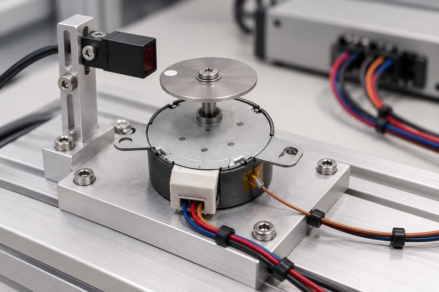
A backlash requirement should reflect how the machine actually reverses, rather than relying exclusively on a static measurement from a lightly loaded mechanism. Operating conditions influence both immediate positioning behavior and long-term wear.
Define the representative load spectrum
Document the expected torque in both rotational directions, including normal operating loads and credible peak demands. Include acceleration, deceleration, output speed, and the inertia reflected through the transmission.
Describe how frequently reversals occur and how the machine distributes them throughout a production cycle. Occasional indexing and repeated short-stroke reciprocation can impose substantially different operating demands.
Record dwell periods, direction changes, and representative motion profiles where they affect loading. Include starts, stops, and load changes that materially influence the gearbox’s mechanical operating conditions.
External forces can change tooth contact, bearing loading, and shaft deflection. Where relevant, document radial or axial loads, mounting orientation, and any load imbalance that may affect measured performance.
Establish application-specific backlash limits
Start with the maximum positioning error permitted by the machine. Allocate an appropriate portion to gearbox lost motion after accounting for screw backlash, coupling effects, structural deformation, and other relevant contributors.
Set a new-unit limit for incoming inspection or initial commissioning. Define whether it applies to clearance-only backlash or reported total lost motion, and preserve the same measurement convention throughout supplier documentation.
Set a separate end-of-life limit based on the machine’s required positioning performance and expected service conditions. The permissible increase from the initial condition should follow the available error budget, not an assumed universal wear allowance.
Neither limit should be selected from an unsupported generic precision class. Gear structure, manufacturing characteristics, loading, and application requirements differ, so suitability must be established for the particular geared motor configuration.
Validate service-life assumptions against operating conditions
Define the required service period and the operating duty expected throughout that period. Express the duty in meaningful terms, such as operating hours, completed cycles, reversal events, or another traceable measure.
A credible service-life estimate must reflect the specified reversal frequency, applied load, operating temperature, and other relevant duty conditions.
Specify representative load, reversal pattern, operating temperature, maintenance assumptions, and other factors relevant to the proposed application.
Request evidence that supports the required initial and end-of-life limits under comparable conditions. If available endurance data uses a different load spectrum or measurement method, identify the difference before applying its results to the design.
Wear does not necessarily progress at a constant rate. Avoid extrapolating a short initial test into a lifetime guarantee without supporting evidence, particularly when the intended application involves frequent reversals or changing loads.
Finally, connect the mechanical requirement to the machine’s lifecycle needs. The specification should establish acceptable performance when new and after representative service, while leaving the detailed static and dynamic acceptance procedures to the verification plan.
Validate Static and Dynamic Performance
A complete verification plan should separate gearbox lost-motion measurement from powered axis positioning tests. These tests answer different questions and require different measurement arrangements, operating conditions, and acceptance criteria.
Perform the static torque-reversal test
Restrain the motor input using a defined fixture, then apply controlled positive and negative torque to the gearbox output. Measure output angular movement between specified torque endpoints without assuming the output remains stationary.
The recorded angle represents total movement under the chosen loading conditions unless the measurement method separates clearance from elastic deformation. Report the result as output lost motion when those contributions cannot be distinguished reliably.
Use an output encoder when direct angular measurement is practical. Specify its resolution, calibration status, mounting arrangement, and measurement location so readings correspond to the gearbox output rather than an upstream component.
A dial indicator can measure tangential displacement at a known effective radius. For small angular changes, angular displacement in radians is approximately tangential displacement divided by the effective radius; document the geometry and conversion method.
Check whether the indicator bracket, fixture, shaft, or coupling introduces additional movement. Where practical, characterize fixture compliance independently and account for its contribution without assuming that every measured displacement originates inside the gearbox.
Repeat measurements under representative conditions
Define a consistent conditioning procedure before collecting readings. Specify any initial operating cycles, loading sequence, stabilization period, and measurement timing, then apply the same procedure to every sample being compared.
Repeat the test across relevant output positions, both torque directions, and representative operating temperatures. Record individual readings as well as the reported result, particularly when position-dependent contact or measurement variation affects the observed range.
Evaluate measurement uncertainty from instrument calibration, resolution, alignment, repeatability, fixture deformation, and the method used to identify torque endpoints. The uncertainty statement should explain which effects are included and how the combined result is calculated.
Do not treat a reading close to the specified limit as an automatic pass when uncertainty could change the decision.
Define the acceptance decision rule beforehand, including any required guard band or procedure for inconclusive results.
Test powered commanded reversals separately
A powered test evaluates how the complete axis responds when the controller commands movement in opposite directions. Unlike the static test, the motor is energized and operating through its specified motion profile.
Use an output encoder or independent linear measurement system to record actual movement and position.
Define the measurement reference relative to the commanded coordinate, and ensure sensor placement does not conceal screw, coupling, or structural errors.
Run representative reversals at relevant speeds, accelerations, loads, travel positions, and temperatures. Include the operating conditions most likely to expose missed steps, settling delays, compliance, or direction-dependent positioning differences.
Record commanded and measured positions throughout the reversal sequence. Evaluate the selected application metrics, such as reversal error, repeatability, settling behavior, and final position deviation, without attributing every discrepancy to gearbox backlash.
Apply separate new-unit and end-of-life criteria
Establish initial acceptance limits for incoming inspection and commissioning. Define the permitted static lost motion and dynamic axis errors independently, using the machine’s error budget and required operating performance.
For end-of-life evaluation, repeat the documented measurements after representative endurance conditioning. The conditioning must reflect the specified reversal duty and load spectrum rather than an arbitrary number of cycles.
Compare results against the corresponding lifecycle limits, accounting for changes in temperature, preload, and other controlled conditions. If the measurement setup changes, establish whether results remain comparable before interpreting differences as wear.
| Test type | Recorded result | Acceptance requirement |
| Static torque reversal | Output lost motion under defined torque endpoints | Application-defined maximum for a new unit |
| Powered reversal | Measured axis reversal error and repeatability | Application-defined limits under representative operating conditions |
| Repeatability and uncertainty | Individual readings, variation, and measurement uncertainty | Predetermined decision rule and documented uncertainty allowance |
| End-of-life verification | Static and dynamic results after defined endurance conditioning | Application-defined lifecycle limits under specified test conditions |
Define supplier records and sample approval
Require the supplier to identify the tested motor and gearbox configuration, sample serial numbers, reduction ratio, and relevant mechanical interfaces. Records should distinguish verified configuration details from unconfirmed assumptions.
Include the complete test method, revision number, instrument identification, calibration status, fixture arrangement, temperature, preload, torque endpoints, conditioning procedure, and raw measurement results.
Keep the calculation procedures, quantified measurement uncertainty, pass/fail decision criteria, and departures from the approved test protocol in the verification records.
Where endurance testing is required, retain the applied load spectrum, reversal profile, conditioning history, and corresponding post-test measurements.
Before production approval, both parties should review the results against the agreed specification.
The signed sample acceptance record should identify the approved configuration, applicable initial and lifecycle limits, test-method version, outstanding deviations, and authorization for release.