
A geared stepper motor must transmit torque while its output shaft and internal supports withstand forces from attached pulleys, gears, couplings, and driven mechanisms. These are different checks.
A reliable specification therefore describes the applied load, its direction, where it acts, and the operating conditions—not just a single maximum figure.
1. What Radial Load Rating Applies at the Specified Reference Distance?
Output torque describes the twisting action available to drive a mechanism. Radial load is a force perpendicular to the output-shaft axis, often introduced by a belt, pulley, gear mesh, or misaligned coupling.
Axial loading refers to force directed along the output shaft’s centerline. Neither force is interchangeable with torque, and a gearbox’s rated output torque does not by itself establish its allowable radial or axial shaft load.
When requesting a radial-load rating, ask the supplier to define the reference distance precisely.
It may be measured from a mounting face, bearing datum, or another drawing-defined point to the line where the external force acts.
Do not assume that a rating applies at the shaft tip or at the center of an attached pulley.
Moving the same force farther from the supported shaft changes the bending moment and may change the allowable load.
The rating also needs its boundary conditions. Confirm the specified output speed, mounting orientation, load direction, bearing arrangement, and whether the value represents a static limit, an operating limit, or another defined criterion.
Use the geared stepper motor range as the starting point for a supplier discussion, then provide the actual mechanism drawing and load conditions for confirmation rather than inferring a rating from a general product description.
A useful request identifies both the force and its point of application.
Include shaft extension, pulley or gear position, mounting face, and any external support so the supplier can evaluate the same geometry the machine will use.
2. What Axial Load Is Allowed in Each Direction?
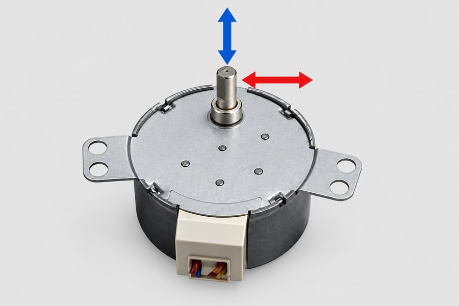
Axial force can push the shaft into the gearbox or pull it away from the housing.
These directions may not share the same allowable value, so ask for limits separately rather than reporting only an unsigned force.
State whether thrust is continuous, intermittent, or a short-duration peak. Also identify output speed and mounting orientation, because the applicable rating may depend on operating conditions and how the assembly is installed.
Describe the source of thrust: a helical gear, screw mechanism, preload, coupling arrangement, or actuator can produce different force patterns. If force changes direction during a cycle, provide both directions and the reversal frequency.
Do not treat a shaft’s ability to transmit torque as evidence that it can withstand a particular axial force. Torque concerns rotation; thrust concerns force along the shaft and the internal path that reacts it.
For vertical or inclined mechanisms, include gravity-driven thrust and the load state during startup, stopping, holding, and power-off conditions. Distinguish forces carried by the gearbox from those intercepted by a separate machine bearing.
3. How Must Combined Radial and Axial Loads Be Verified?
A design may apply radial force and axial thrust at the same time.
Checking each force against its own independent maximum is not sufficient unless the supplier explicitly confirms that the ratings can be combined under those conditions.
Combined loading can change the demands on the shaft and supporting bearings.
The permitted combination may depend on force directions, application points, output speed, mounting arrangement, and whether the loads occur continuously or only during part of the cycle.
Send a load schedule that pairs the radial and axial forces occurring at each operating state.
Include their directions, duration, speed, starts and stops, and any transient events instead of submitting separate maximum values without context.
| Load case | Information to provide | Supplier confirmation needed |
| Radial force only | Direction, magnitude, reference distance, output speed | Applicable radial-load limit and assumptions |
| Axial thrust only | Push/pull direction, magnitude, duration, speed | Direction-specific thrust limits |
| Simultaneous radial and axial forces | Both forces, application points, directions, timing | Approved combined-load criterion for the stated conditions |
| Transient or reversing load | Peak event, repetition rate, cycle description | Whether the event is permitted and how it affects duty assessment |
If the supplier provides only separate ratings, ask what method should be used to assess the combined case. Do not invent a linear interaction rule or assume that operating below both individual maxima proves acceptability.
Keep static and dynamic cases distinct. A brief peak may govern immediate strength, while repeated combined loads can influence fatigue and service life; the supplier needs enough cycle information to evaluate both.
For an uncertain load path, first identify which component reacts each force.
A machine-side bearing may carry some radial or axial load, but that assumption must be reflected in the actual layout and validated with the supplier.
4. How Do Actual Overhang and Bending Moment Affect Shaft Support?
A radial force applied beyond the gearbox’s supporting bearing creates a bending moment. Its effect depends on the force magnitude, perpendicular offset, shaft geometry, and internal support arrangement.
For a simple illustration, suppose a hypothetical pulley applies a 10 N radial force at a perpendicular distance of 0.02 m from the selected reference point. The resulting bending moment is 0.2 N·m.
This example illustrates the calculation, not an allowable product load. The supplier must evaluate the actual shaft, bearing arrangement, load direction, operating speed, and applicable rating conditions before approving the design.
The calculation uses the perpendicular distance between the reference point and the force’s line of action.
If the force is not perpendicular to the offset, use the appropriate perpendicular component rather than multiplying by the full distance indiscriminately.
Bending moment = applied force × perpendicular lever arm.
Here, M represents the moment about the reference point, F is the applied force, and the perpendicular lever arm is its perpendicular lever arm. The result is expressed in newton-metres.
Although bending moment and transmitted torque share the same physical units, they describe different mechanical effects. Transmitted torque drives rotation, whereas bending moment loads the shaft transversely and increases demands on its supporting structure.
Separate external forces from bearing reactions
A gear mesh can introduce radial and tangential forces, while a helical gear may also generate axial thrust. Their directions and magnitudes depend on the gear geometry and operating conditions.
Calculate the forces at the actual mesh or pulley location, then identify how the shaft, gearbox bearings, and any external supports react them.
Do not treat the applied gear force and bearing reaction as interchangeable quantities.
An external support bearing may reduce the load carried by the gearbox, but only if its position, stiffness, alignment, and load path justify that assumption.
A nominal support on a drawing does not establish effective load sharing.
Ask the supplier which reference point and support assumptions govern the stated shaft-load limits. If the mechanism uses an extended shaft, pulley, or gear, provide its dimensions and force application point for review.
The installation drawing should show the gearbox mounting face, output-shaft extension, force direction, overhang distance, external bearing positions, and relevant attachment dimensions.
This lets both parties assess the same geometry instead of comparing unrelated load figures.
5. How Do Shock Loads, Reversals, and Duty Cycle Affect Allowable Loading?
A mechanism’s maximum force does not fully describe its operating demand. Short impacts, repeated acceleration, frequent reversals, and sustained loading can produce different stresses and fatigue exposure over time.
Separate static peak loads from recurring operating loads in the specification.
A brief disturbance may govern an instantaneous limit, while a smaller force repeated throughout production may require a different assessment of fatigue and service life.
Identify where impacts originate, such as a mechanical stop, abrupt engagement, product collision, or sudden change in driven resistance. Include the estimated peak magnitude and duration when known, and explain how often the event occurs.
Reversing mechanisms need particular attention because the direction of shaft force may change repeatedly. Report reversal frequency, acceleration and deceleration profiles, dwell periods, and whether radial or axial forces reverse alongside the transmitted torque.
Do not assume that reversing torque necessarily reverses every shaft load. A belt may maintain approximately the same radial-force direction, while a reversing gear train or moving mechanism may change the direction of specific forces.
Describe the complete operating cycle rather than giving only average speed. Include startup, steady operation, stopping, idle intervals, and any periods when the mechanism holds a load while the motor remains energized.
Duty information should distinguish occasional operation from sustained production. Relevant details include operating hours, cycles per hour, expected lifetime cycles, ambient conditions, and changes in load between product types or machine recipes.
The supplier can then determine which load limits apply and whether additional validation is necessary. Do not infer a universal service-life figure from a static load rating or an isolated peak-load test.
When the machine includes abnormal events, document them separately from normal operation. If jams, emergency stops, or collisions are credible, explain their expected frequency and how the mechanism limits or transfers the resulting forces.
6. How Should the Shaft Connection Be Installed Without Damaging Bearings?
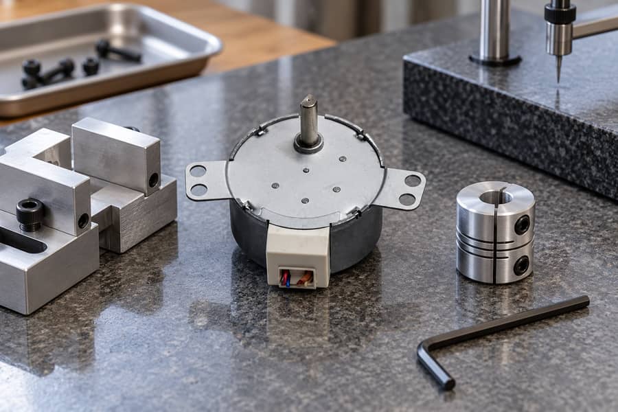
The shaft-to-hub connection must transmit the required torque without introducing unacceptable radial forces, axial thrust, or bending. Specify the mating geometry and assembly method together, rather than selecting a coupling solely by nominal shaft diameter.
Provide the shaft diameter, usable engagement length, keyway or flat dimensions where applicable, and the intended hub or coupling fit. Include tolerances and alignment requirements needed to prevent interference or excessive movement.
A press-fit hub may require substantial axial assembly force.
If that force passes through the output shaft into the gearbox’s internal bearings, it can damage or overload components unless the supplier explicitly approves that installation method.
Design the assembly procedure so pressing force is reacted through a suitable fixture or supported component whenever required.
Confirm the permissible force path with the supplier before deciding where installation tools should contact the shaft or hub.
Do not hammer a hub, pulley, or coupling onto the output shaft without an explicitly approved procedure. Impact can transmit uncontrolled loads through the shaft and bearings, even when the finished assembly appears correctly positioned.
Check coupling alignment before final tightening. Angular or parallel misalignment can create additional radial forces during rotation, while axial misalignment may introduce thrust or constrain thermal movement in the assembled mechanism.
Also review fasteners, keys, clamping elements, and retaining features for their intended roles. A component that prevents axial movement does not automatically correct misalignment or establish that the shaft’s allowable load limits are respected.
For assemblies using external bearings, confirm that the gearbox and external support share a common alignment strategy. Incorrect positioning can create preload or unintended reactions that undermine the assumed load distribution.
Before approving the connection, document the specified fit, assembly tools, support fixture, alignment method, and inspection criteria. Request supplier approval for any installation force or procedure that could load the internal bearings.
7. What Load-Life Evidence and Acceptance Tests Should Buyers Request?
A supplier’s load rating is useful only when its operating assumptions match the intended application. Buyers should request documented evidence connecting the specified loads, operating cycle, installation arrangement, and acceptance criteria.
Establish the Basis for Load-Life Claims
Ask how the supplier establishes allowable radial and axial loads, including the reference distance, force direction, output speed, mounting orientation, and bearing-support assumptions. Confirm which conditions apply simultaneously.
Service-life estimates require more than a maximum-load figure. The supporting basis should identify relevant load magnitudes, operating duration, speed, temperature, reversals, and other conditions that materially affect the assessment.
Request the distinction between a static strength limit, a permitted operating load, and a fatigue-related or service-life criterion. These describe different engineering concerns and should not be substituted for one another.
Where calculated life or endurance evidence is available, ask which assumptions and failure criteria underpin it. A calculated bearing lifespan does not establish how long the entire geared motor assembly will reliably operate.
The stepper motor range provides broader configuration context, but application-specific shaft loading still requires confirmation against the selected assembly and its actual operating conditions.
Verify Performance Under Representative Application Conditions
An acceptance test should reproduce the important mechanical features of the intended installation. These include shaft overhang, external support locations, force directions, coupling arrangement, mounting orientation, and the relevant operating speeds.
Structure the testing program around the full range of loads encountered during actual machine operation, including their variations over time.
Include normal running, acceleration, deceleration, reversals, dwell periods, and credible transient events where they affect the specified requirements.
Record the initial condition before testing, including shaft movement, relevant dimensions, operating temperature, noise or vibration where specified, and any positioning measurements applicable to the mechanism.
Repeat measurements under controlled conditions so observed differences can be distinguished from fixture movement, measurement uncertainty, temperature changes, and ordinary unit-to-unit variation.
Define the Test Envelope and Safety Controls
Agree on the test envelope with the supplier before applying external loads. The approved envelope should identify permitted load combinations, speed ranges, operating durations, mounting arrangements, and any restrictions on transient events.
Never exceed documented limits simply to discover where a shaft or bearing fails. Tests beyond the approved envelope require a separately reviewed engineering plan and appropriate containment, not an improvised production acceptance procedure.
Secure the motor and loading fixture against movement, and guard exposed rotating shafts, couplings, pulleys, and other moving parts. Keep personnel clear of potential release paths and use remote measurement where practical.
Define stop conditions before testing begins. These may include exceeding documented temperature limits, unexpected movement, abnormal noise, unstable vibration, fixture displacement, or any other application-specific indication of unsafe operation.
Separate Incoming Acceptance from Endurance Testing
Incoming acceptance determines whether a delivered unit meets agreed requirements. It typically checks identification, dimensions, shaft condition, installation interfaces, and specified functional measurements without claiming to establish full service life.
Endurance testing evaluates behavior over a defined operating cycle and duration. It may reveal wear, increasing lost motion, loosening, temperature-related changes, or other degradation that a brief incoming inspection cannot establish.
Passing a brief operational check cannot demonstrate that the assembly will maintain acceptable performance throughout its intended working life.
Conversely, an endurance test on one sample does not automatically establish that every delivered unit meets dimensional or functional acceptance requirements.
Agree on sample quantities, test duration, inspection intervals, failure definitions, and disposition rules before endurance testing.
Where testing is performed by the supplier, request traceable results and an explanation of how the evidence applies to the proposed configuration.
Quantify Repeatability and Record Changes
Choose measurements that directly reflect the application’s mechanical requirements. Depending on the design, these may include shaft displacement, axial movement, radial movement at a defined location, temperature, vibration, or positioning repeatability.
Record the baseline before loading or endurance testing, then repeat the same measurements using consistent fixtures, reference points, instruments, and operating conditions. Document any configuration changes between measurement stages.
Quantify repeatability using an agreed metric, such as the observed range across repeated cycles or the spread of repeated readings. Report instrument resolution and measurement uncertainty so small differences are not mistaken for meaningful degradation.
Separate repeatability from absolute positioning accuracy. A mechanism may return consistently to the same position while retaining an offset from its intended target; the two characteristics require different acceptance criteria.
The acceptance limits must come from the application requirements and supplier-approved specifications. If a measured result exceeds its limit, document the deviation and obtain engineering disposition rather than silently adjusting the acceptance threshold.
| Test stage | Measurements and evidence | Acceptance basis |
| Incoming inspection | Identification, dimensions, shaft condition, interface checks | Approved drawing and purchase specification |
| Initial functional test | Shaft movement, temperature, specified operating behavior | Agreed baseline and functional limits |
| Representative-load test | Radial and axial loading, speed, temperature, repeatability | Supplier-approved test envelope and application requirements |
| Endurance test | Periodic measurements, wear indicators, changes from baseline | Agreed duration, failure criteria, and degradation limits |
| Post-test inspection | Dimensional changes, looseness, damage, functional results | Documented post-test acceptance criteria |
Prepare a Complete Supplier-Data Handover
Submit the final application drawing with the gearbox mounting face, shaft dimensions, overhang distances, external supports, attachment geometry, and clearly marked force directions. Include calculated bending moments and identify their reference points.
Attach the load spectrum, operating speeds, duty cycle, transient events, mounting orientation, installation procedure, and proposed acceptance limits. Mark uncertain values explicitly so the supplier can identify which assumptions require confirmation.
Request written confirmation of applicable radial and axial ratings, permitted combined-load conditions, installation-force restrictions, supporting life evidence, and the approved verification method.
Retain the approved drawing revision, test records, measured results, deviations, and final acceptance decision with the selected configuration.