
Hybrid stepper motors are often offered with different native step angles, leading engineers to ask whether a smaller angle automatically produces more accurate machine positioning.
The answer depends on what is being measured: commanded resolution, absolute positioning error, repeatability, or motion under the actual load and drive conditions during operation.
What Do Resolution, Accuracy, and Repeatability Mean?
Resolution describes the smallest commanded increment represented by the control system. It is command granularity, not proof that the shaft or machine reaches every increment exactly.
Absolute positioning accuracy compares the achieved position with the intended target. Error can vary with position, direction, load, temperature, and the measurement method used.
Positioning repeatability indicates the degree of variation in a machine’s actual stopping locations when it repeatedly approaches the same commanded target under consistent operating conditions.
A mechanism may repeat consistently while remaining offset from its commanded target.
These terms should be specified separately because a finer command increment can coexist with poor absolute accuracy, while repeatability may remain useful for a particular process.
A controller can count every pulse correctly while the rotor fails to follow the intended movement. Command records alone therefore cannot confirm that the machine reached each target.
For a hybrid stepper, native full-step angle is a construction characteristic of the motor’s magnetic and rotor geometry. It is not a driver setting.
The driver can change the commanded subdivision of each full step, but changing the microstep setting does not change the motor’s underlying native angle.
What Does a Smaller Native Step Angle Change?
For a rotary shaft, nominal full steps per revolution follow from dividing 360 degrees by the native step angle. This arithmetic describes command geometry only.
A 1.8° motor requires 200 nominal full steps for one revolution, while a 0.9° motor requires 400. A 0.45° option corresponds to 800.
| Native step angle | Nominal full steps per revolution | What the figure establishes |
| 0.45° | 800 | More nominal full-step increments per revolution |
| 0.9° | 400 | Twice the nominal full-step count of 1.8° |
| 1.8° | 200 | Fewer nominal full-step increments per revolution |
Leili Motor lists 0.45°, 0.9°, and 1.8° options across its hybrid stepper motor family; availability should be checked for the specific motor configuration.
A smaller native angle offers more nominal full-step positions per revolution. It does not establish that each position will be reached with proportionally lower error.
For example, the geometric step count doubles when moving from 1.8° to 0.9°, but that arithmetic alone does not show the shaft’s true deviation from each target.
The practical benefit depends on motor torque characteristics, drive behavior, load, and application requirements. Compare candidates using the same duty cycle and measurement criteria.
A smaller angle may be useful when its additional native positions suit the required movement increments, but application-level accuracy still requires direct verification.
For rotary-to-linear systems, the nominal motor increment is only the starting point. The transmission’s conversion ratio determines the corresponding theoretical linear command increment.
That calculation still describes commanded motion rather than measured carriage accuracy. Engineers should avoid treating a smaller calculated increment as proof of improved machine performance.
For a rotary table or linear axis, the transmission ratio changes the output increment. Label this conversion as nominal unless it has been verified through measurement.
Do Microsteps Improve Actual Positioning Accuracy?
Microstepping lets a compatible driver command intermediate electrical current states between full-step positions. The controller can issue smaller nominal increments without changing the motor’s construction.
Those increments are not guaranteed to produce equal shaft movements. Rotor position depends on available electromagnetic torque and the opposing torque from the load and mechanism.
Friction and detent torque can prevent small commands from creating visible motion until accumulated torque becomes sufficient. This may cause uneven movement despite fine pulse commands.
Torque ripple and load angle also influence the rotor’s equilibrium position. Under load, actual microstep spacing can depart from the ideal spacing assumed by command calculations.
At very small commanded increments, the rotor may remain near its previous equilibrium instead of following each command as a distinct, equally sized movement.
Actual response can vary across a revolution because magnetic torque and friction do not remain perfectly uniform at every commanded position.
Motor step-angle tolerance adds another distinction: nominal full-step geometry is not an exact guarantee for every physical position. Consult specified motor data rather than infer tolerances from angle alone.
Microstepping can improve motion smoothness, reduce excitation of some resonances, and provide finer command granularity. Those benefits should not be presented as equivalent to absolute positioning accuracy.
Assess microstepping through observed movement and settling behavior, rather than relying only on the microstep count displayed in the driver configuration.
Increasing subdivision also raises command-pulse requirements for a given shaft speed. The controller and driver must accept the necessary pulse rate without dropping commands.
For selection, treat native step angle and microstep setting as separate design choices. Verify the combination against load behavior, usable torque, speed, and required positioning results.
Which Mechanical and Thermal Errors Limit Machine Accuracy?
Backlash, Lead Error, and Elastic Deflection
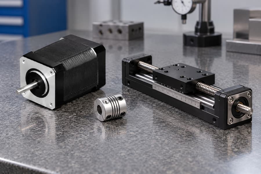
A finer motor command cannot eliminate clearance within a gearbox, screw nut, or other transmission. During reversals, movement may be consumed before the output changes direction.
Backlash matters particularly for bidirectional positioning. A machine approaching the same target from opposite directions can settle at different locations despite identical commanded step counts.
Leadscrew pitch error creates another limitation. Even when a motor completes the intended rotation, the resulting linear travel may deviate from its theoretical conversion.
Pitch variation can produce position-dependent error, while accumulated lead error becomes more apparent over longer travel. Specifications should distinguish local repeatability from travel-wide accuracy.
Couplings, belts, brackets, and shafts also deflect under force. Their elastic movement changes with load direction and magnitude, creating offsets that finer steps cannot correct.
At higher acceleration, elastic components may oscillate after a commanded stop. Measuring final position before settling can exaggerate apparent motor error or conceal transient positioning problems.
Friction complicates small movements through sticking and sudden release. A commanded increment may initially produce stress in the transmission rather than measurable displacement at the working point.
Alignment, Structural Support, and Measurement Position
Misaligned screws, guideways, and motor shafts introduce side loading and variable resistance. The resulting motion errors can change throughout the stroke or after assembly adjustments.
A flexible machine frame may tilt or bend when tooling contacts a workpiece. Measuring only motor-shaft rotation will not capture displacement occurring between the motor and tool.
Measurement location therefore matters. An encoder mounted upstream of a loose coupling may report accurate rotation while the driven carriage or fixture remains displaced.
Engineers should define the functional measurement point and operating force before comparing motors. Otherwise, component-level tests can overlook errors that determine machine performance.
Temperature and Changing Operating Conditions
Thermal growth affects screws, frames, fixtures, and measurement references. A machine calibrated cold may show different absolute positions after reaching its normal operating temperature.
Uneven heating is especially important because temperature gradients can distort alignment, not merely lengthen parts uniformly. Nearby drives, bearings, and process equipment may contribute heat.
Temperature can also alter lubricant behavior, friction, bearing preload, and structural constraints. These changes may affect settling and reversal behavior even without measurable motor-step errors.
Motor winding temperature changes electrical resistance, while driver regulation and available torque depend on the operating configuration. Verify performance after thermal stabilization, not only at startup.
For meaningful comparisons, record load, position, travel direction, and thermal state. These conditions explain whether an observed difference reflects the motor, transmission, or machine structure.
How Do Load, Speed, and Driver Settings Affect Performance?
Torque, Inertia, and Acceleration
The selected motor must supply torque throughout the commanded motion, not simply hold the load when stationary. Acceleration adds demand beyond steady-speed operation.
Load inertia, reflected through the transmission, influences required acceleration torque and dynamic response. Large inertial mismatches may increase settling time or make missed steps more likely.
Evaluate each candidate using its documented torque-speed curve under applicable drive conditions. Holding torque alone cannot establish available torque at the required running speed.
A smaller native step angle does not inherently deliver greater available torque or better accuracy. Compare actual configurations rather than assuming equivalent characteristics from matching dimensions.
Resonance and Motion Profiles
Stepper systems can exhibit resonance where excitation interacts with mechanical dynamics. Susceptible speed bands depend on the motor, driver, load inertia, coupling, and mounting.
Microstepping and controlled acceleration can improve behavior in some conditions, but neither guarantees stable motion across the entire speed range. Test both steady running and transitions.
A rapid start, abrupt reversal, or aggressive ramp may demand more torque than remains available. Shape motion profiles around measured operating margins and required settling times.
Pulse Rate and Electrical Compatibility
Pulse demand rises with full steps per revolution, microstep subdivision, and shaft speed. Controller output capability and driver input limits must accommodate the entire motion profile.
As an illustrative calculation, a 0.9-degree motor has 400 native full steps per revolution. At 60 rpm, that equals one revolution each second.
With 16 microsteps per full step, its required command rate is 400 x 16 x 1 = 6,400 pulses per second for that constant speed.
For a 1.8-degree motor, the equivalent calculation is 200 x 16 x 1 = 3,200 pulses per second. Neither figure is a product rating.
Faster operating speeds increase pulse demand, while acceleration requires reliable pulse timing. Check controller frequency, driver timing, and command delivery throughout the complete motion cycle.
Match the driver’s phase-current capability and current-setting convention to the specified motor winding. Confusing peak and RMS values can lead to inappropriate settings.
Supply voltage must remain within driver limits and suit the motor-drive combination. Available voltage influences current buildup at speed, but higher voltage does not automatically improve accuracy.
Also confirm winding connections, inductance-related behavior, thermal limits, and protection settings against approved documentation. Electrical compatibility is necessary before comparing positioning performance.
Use representative motion cycles to assess missed steps, heating, vibration, and settling. Select the angle and drive combination that meets measured requirements under realistic conditions.
How Should Engineers Budget and Validate Positioning Errors?
Define Accuracy Requirements at the Working Load
Begin with the machine’s functional requirement rather than the motor specification. Define allowable absolute positioning error, repeatability, and settling behavior at the actual working point.
Specify the measurement location, travel range, load magnitude, approach direction, and operating temperature. These conditions establish which deviations matter to the finished machine.
Separate systematic errors from random variation. A consistent offset may be correctable through calibration, while changing backlash, friction, or deflection requires different engineering controls.
Create an error budget that assigns each significant source an estimated contribution. Include motor positioning error, transmission inaccuracies, structural movement, temperature effects, and measurement uncertainty.
Use supplier specifications, engineering calculations, and preliminary measurements to establish initial estimates. Replace assumptions with measured values as the machine design becomes available for testing.
Do not automatically combine every error using a statistical formula. Correlated errors, predictable offsets, and direction-dependent effects may require different treatment from independent random variations.
For conservative planning, examine credible combinations of maximum errors. Statistical methods may be appropriate when distributions and independence assumptions are supported by sufficient measurement evidence.
Establish Representative Validation Conditions
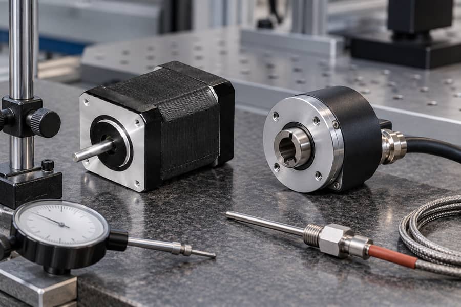
Test positioning at the load rather than relying exclusively on motor-shaft movement. The measurement system should capture displacement at the location governing machine performance.
Begin with a cold machine under documented startup conditions. Measure commanded positions across the required travel range, including endpoints and intermediate locations relevant to production.
Repeat measurements after representative operation brings the assembly into its normal warm condition. Record temperatures at locations influencing alignment, transmission behavior, and positioning drift.
Perform repeated approaches from both directions. Comparing forward and reverse results helps identify lost motion, direction-dependent friction, and elastic deformation that single-direction testing can miss.
Include realistic payloads, acceleration profiles, dwell periods, and operating speeds. Unloaded measurements alone cannot establish accuracy when working forces significantly change the mechanism’s behavior.
Measure actual position after a defined settling interval. Where motion accuracy matters during travel, record following error or trajectory deviation separately from final stationary positioning results.
Document Error Sources and Acceptance Criteria
The following table connects important error sources with practical measurements. Each acceptance limit must reflect the machine’s requirements rather than an assumed universal motor tolerance.
| Error source | Measurement method | Acceptance basis |
| Motor positioning deviation | Compare commanded and measured shaft positions | Specified motor accuracy under documented conditions |
| Backlash and lost motion | Measure displacement during controlled direction reversals | Maximum permitted bidirectional positioning error |
| Transmission lead error | Compare actual output travel against commanded travel | Allowable error across the working stroke |
| Elastic deflection | Measure working-point displacement under representative forces | Maximum allowable load-dependent offset |
| Thermal drift | Compare cold and stabilized warm position measurements | Permitted position change over operating temperatures |
| Repeatability | Repeat identical positioning cycles at selected locations | Application-defined repeatability limit |
| Dynamic settling | Record position response after representative moves | Required settling time and residual error |
Analyze Measurement Results and Uncertainty
Use measurement equipment with suitable resolution, calibration, and uncertainty for the specified tolerance. Instrument readings should be sufficiently reliable to support meaningful acceptance decisions.
Collect enough repeated observations to distinguish consistent offsets from cycle-to-cycle variation. Record individual measurements or distributions rather than reporting only the most favorable result.
Compare absolute error, repeatability, reversal behavior, and thermal drift separately. A machine passing one criterion should not automatically be considered compliant with the others.
Where uncertainty affects a pass/fail decision, establish an agreed decision rule before testing. Preserve raw measurements, calibration records, and operating conditions for later engineering review.
When Is an Encoder Needed, and How Should Engineers Select a Motor?
Decide Whether Open-Loop Control Is Sufficient
Open-loop operation may be appropriate when load conditions are predictable, adequate torque margin exists, and demonstrated positioning performance satisfies the machine’s requirements.
An encoder becomes useful when detecting missed motion, monitoring position, or correcting deviations is necessary. However, feedback performance depends on sensor location and controller implementation.
A motor-mounted encoder measures rotor movement and can support closed-loop motor control. It cannot directly observe backlash or elastic displacement occurring downstream within the transmission.
Load-side feedback measures actual movement closer to the controlled output. It can reveal transmission-related positioning deviations that would remain invisible to a motor-mounted encoder.
However, load-side sensing does not eliminate mechanical errors. Compensation capability depends on measurement location, control bandwidth, mechanical behavior, and the available correction authority.
For demanding applications, evaluate whether motor feedback, load-side feedback, or combined sensing provides the required observability and control performance without unnecessary system complexity.
Select the Native Step Angle Using Verified Performance
Compare candidate motors using equivalent machine requirements, not assumed advantages from nominal step counts. Each configuration needs suitable drive settings and its own verified operating performance.
Review available configurations within Leili Motor’s stepper motor range, confirming native step angle, winding characteristics, torque-speed documentation, and compatibility for the selected application.
Request supplier-supported specifications and measurement methods. Do not substitute nominal microstep resolution for demonstrated accuracy, or assume differently constructed motors deliver identical dynamic behavior.
Before approval, define the selected motor and driver configuration, supply conditions, current settings, pulse requirements, mechanical installation, and representative operating duty.
The acceptance record should contain measured absolute error, repeatability, reversal error, thermal drift, settling performance, test uncertainty, and compliance with agreed machine-specific limits.
Finalize the selected native step angle only after documenting the test configuration, approved component revisions, measurement evidence, and acceptance authorization for the actual machine.