
Captive and non-captive PM stepper linear actuators differ mainly in how their lead screws are guided, restrained, and moved. These arrangements affect output motion, installation interfaces, and mechanical support requirements.
A third configuration uses a rotating screw and translating nut. Understanding all three mechanisms helps engineers evaluate actuator geometry, load paths, travel clearance, and external guidance before selecting a design.
Understanding the Three PM Stepper Linear Actuator Architectures
Captive PM Stepper Linear Actuator
A captive PM stepper linear actuator typically incorporates an internal anti-rotation mechanism and output guide. Its translating shaft or lead screw extends from the actuator while remaining rotationally restrained.
The permanent magnet rotor rotates when the motor receives electrical pulses. An internal screw-and-nut arrangement converts this rotation into linear displacement, allowing the output member to extend or retract.
The integrated guidance maintains the output member’s orientation during movement. This makes the actuator relatively self-contained because the basic anti-rotation function does not depend on an external machine guide.
However, internal guidance should not be interpreted as unlimited structural support. The actuator’s allowable radial loading, bending moment, and axial thrust still depend on its bearing arrangement and mechanical construction.
Non-Captive PM Stepper Linear Actuator
A conventional non-captive PM stepper linear actuator commonly uses a rotating threaded nut connected to the motor rotor. The lead screw engages this nut and moves axially when the rotor turns.
Unlike the captive arrangement, the translating screw generally lacks an integrated anti-rotation guide. An external restraint must prevent the screw from rotating while allowing it to move freely along its axis.
This restraint may come from a connected machine component, linear guide, carriage, or purpose-designed mounting interface. The external structure must react the torque generated during operation without restricting the intended translation.
The arrangement provides flexibility in connecting the screw to an existing machine mechanism. However, designers must account for the additional guidance, alignment, and support requirements.
External Rotating-Screw, Moving-Nut Configuration
A third arrangement uses a rotating lead screw and a translating nut. The screw turns within the threaded engagement, causing the nut to advance or retract along its axis.
The nut requires anti-rotation restraint through an external guide or connected mechanism. The screw also needs suitable rotational support, including bearings and an appropriate axial load-reaction arrangement.
This configuration differs fundamentally from the conventional non-captive rotating-nut arrangement. Engineers should therefore identify the actual moving component rather than assuming both designs share the same construction.
Why Actuator Labels Require Drawing Verification
Manufacturers do not always use identical conventions when describing actuator configurations. Captive, non-captive, and related product descriptions should be treated as preliminary identification rather than definitive mechanical specifications.
Leili Motor offers custom permanent magnet stepper motor and lead-screw mechanisms for applications requiring different mechanical output arrangements.
The actual architecture must be established through sectional drawings showing the rotor, threaded components, bearings, output member, and guidance mechanism. Product names and exterior appearance cannot independently confirm the internal construction.
What Rotates, What Translates, and How Motion Is Generated
The main mechanical difference between these actuator arrangements is the relationship between rotor rotation and output translation. Understanding this relationship helps engineers determine which components require restraint and support.
Comparing the Three Motion Arrangements
| Mechanical arrangement | Rotating components | Translating component | Anti-rotation requirement |
| Captive | Rotor and internal drive components | Guided output screw or shaft | Internal actuator guidance |
| Conventional non-captive | Rotor and threaded rotor nut | Lead screw | External screw restraint |
| Rotating-screw, moving-nut | Lead screw | Nut and connected output | External nut restraint |
These descriptions represent common commercial arrangements rather than universal construction rules. Supplier drawings must establish the actual relationship between every rotating, translating, and constrained component.
Anti-Rotation, External Guidance, and Side-Load Requirements
Anti-rotation and external guidance determine how an actuator interacts with the surrounding machine structure. Incorrect assumptions about these interfaces can cause binding, excessive friction, and premature mechanical wear.
Anti-Rotation Torque and Reaction Paths
When a threaded mechanism generates linear movement, it also produces a torque reaction. The actuator or external machine structure must resist the tendency of the restrained component to rotate.
In a captive arrangement, internal guidance typically reacts the output member’s anti-rotation torque. The reaction transfers through the actuator housing and mounting structure into the machine frame.
A conventional non-captive arrangement requires an external restraint for the translating screw. This restraint must withstand the reaction torque while permitting axial movement without excessive friction.
For a rotating-screw, moving-nut arrangement, the external guide restrains the nut. The machine structure must therefore react the corresponding torque through the nut’s mounting and guidance interfaces.
The restraint should be sufficiently stiff to maintain the intended motion. Excessive compliance can produce unwanted rotation, positioning errors, and inconsistent mechanical behavior.
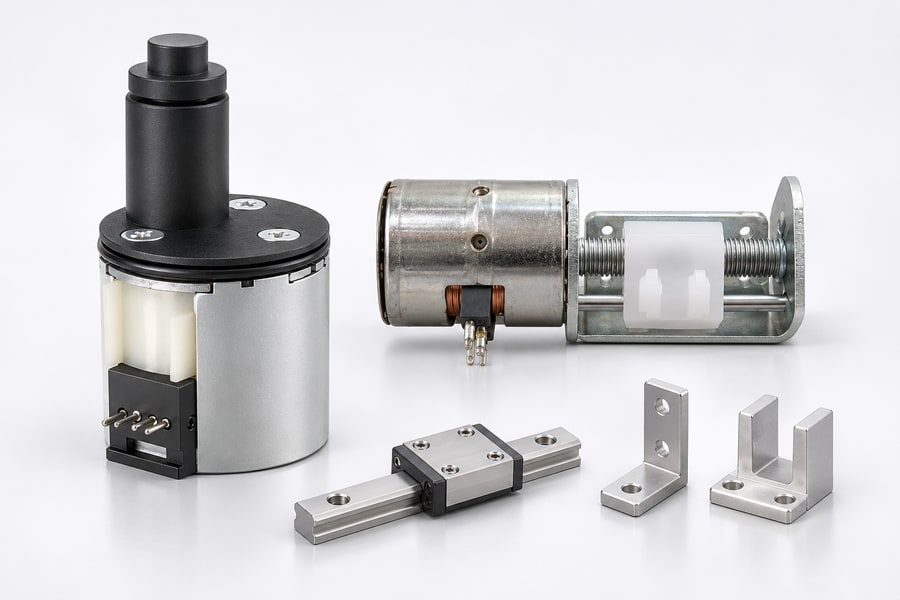
Internal Guidance Versus External Linear Guides
Integrated captive guidance simplifies the basic output arrangement, but it does not automatically replace the machine’s load-support system. The connected load may still require separate linear bearings or structural support.
External linear guides provide controlled movement and can carry loads that should not pass through the actuator screw. They also help maintain the orientation of connected equipment.
For non-captive designs, external guidance usually performs an additional function by preventing screw rotation. Its arrangement must accommodate the complete output stroke without restricting axial movement.
Engineers should distinguish guidance of the screw or nut from guidance of the actual machine load. These functions may require different components and mounting references.
Side Loads, Alignment, and Overconstraint
Axial thrust acts along the actuator axis, whereas radial and lateral forces act across it. These loading conditions produce different stresses and require different support arrangements.
Side loads applied directly to an output screw can cause bending, additional thread friction, and uneven wear. The actuator should not be assumed to carry these forces unless its specified capacity supports that use.
Alignment between the actuator axis and external guide is equally important. Nonparallel mounting surfaces or incompatible reference dimensions can force the screw and guide to follow different paths.
Overconstraint occurs when multiple mechanical elements independently attempt to control the same movement. Manufacturing tolerances, assembly errors, and structural deflection can then produce binding or increased bearing loads.
A suitable design establishes clear locating references and allows the intended components to move without redundant constraints. External guides should support the load without imposing unnecessary lateral forces on the actuator.
Stroke, Installation Space, Thrust Support, and Screw Stability
The actuator’s mechanical arrangement affects more than the direction of output movement. It also determines the required clearance, bearing support, usable travel, and structural stability under operating loads.
Usable Stroke and End-Stop Arrangements
Usable stroke describes the permitted linear movement of the output component under the intended operating conditions. The full threaded travel should not be taken as the permitted output stroke.
Captive actuators may incorporate internal travel restrictions, depending on their construction. Non-captive designs may rely more heavily on external stops or machine-level travel control.
Moving-nut configurations also require sufficient clearance for the nut to travel without contacting bearings, supports, or other mechanical components.
Engineers should identify the permitted travel range and the location of every mechanical stop. The complete assembly must prevent overtravel without using unsuitable internal components as unintended impact surfaces.
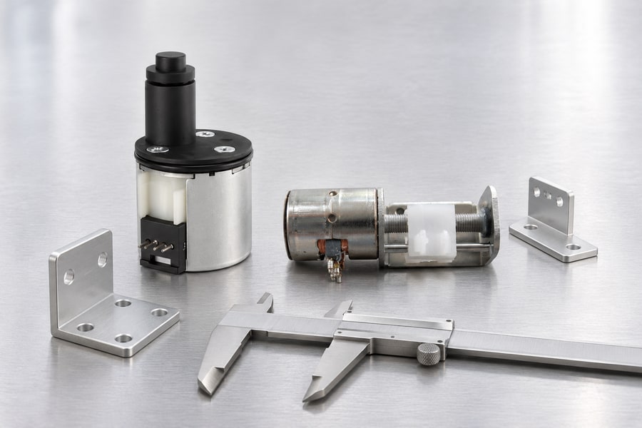
Swept Envelope and Clearance Requirements
Installation space must account for the movement of every component, not simply the motor body’s dimensions. A compact motor housing does not necessarily indicate a compact operating envelope.
For captive actuators, the output shaft extends beyond the housing as the stroke increases. Designers must provide clearance for this movement and the connected load.
Conventional non-captive actuators require additional consideration because the translating screw may extend significantly beyond the motor assembly. Its movement can affect surrounding structures, guards, and machine components.
Rotating-screw, moving-nut configurations have a different clearance requirement. The screw must accommodate its rotating length, while the nut and attached load occupy a changing position along the axis.
The swept envelope should be evaluated on both sides of the actuator. This includes rear-side screw extension, front-side output movement, couplings, brackets, connectors, and maintenance access.
Axial Thrust and Bearing Load Paths
Axial thrust must transfer through an appropriate mechanical load path. Depending on the architecture, this path may involve the screw, threaded nut, thrust bearings, supporting structure, and actuator mounting.
Radial bearings and thrust bearings perform different functions. A bearing arrangement suitable for supporting shaft rotation does not automatically provide adequate axial load capacity.
In captive designs, internal support components react loads generated by the translating output. However, their allowable capacity must be confirmed rather than inferred from integrated construction.
Conventional non-captive arrangements also require confirmation of how the rotating nut and actuator bearings transfer axial reactions. External screw guidance does not independently establish the thrust-bearing capacity.
For rotating-screw arrangements, the support system must accommodate both rotation and axial loading. Designers should verify the actual bearing configuration and avoid applying external forces through components not intended to carry them.
Screw Buckling and Unsupported Length
A translating screw subjected to compression may experience elastic buckling. The risk depends on screw diameter, unsupported length, material properties, and end-support conditions.
Longer unsupported sections generally require closer evaluation. Additional supports may improve stability, but their alignment must be compatible with the screw’s intended movement.
Tensile loading creates a different structural condition and should not be evaluated using compression-buckling assumptions.
Critical speed is relevant to components that actually rotate. Therefore, it should be assessed for the rotating lead screw in a rotating-screw arrangement, using its length, geometry, support conditions, and operating speed.
A translating screw in the conventional non-captive arrangement should not automatically be assigned a rotating-shaft critical-speed requirement. Its structural evaluation should reflect its actual motion and loading conditions.
Operating Performance, Lubrication, Backlash, and Serviceability
The three architectures can produce different mechanical behavior even when their basic motor technology is similar. Performance depends on the complete screw mechanism, external interfaces, loading conditions, and maintenance requirements.
Thrust, Screw Lead, and Motion Performance
Screw lead determines the linear distance traveled during one complete relative revolution between the threaded components. Increasing the screw lead increases linear displacement per revolution and changes the torque needed to deliver a specified axial force.
Available linear thrust depends on motor torque, screw geometry, mechanical efficiency, and operating conditions. Friction in the nut, guide system, and connected mechanism also influences actual output.
A captive actuator includes internal guidance, while a conventional non-captive design depends on external screw restraint. The additional interfaces can affect friction and mechanical compliance.
Rotating-screw arrangements introduce their own bearing and support requirements. Consequently, motor specifications alone cannot establish the complete actuator’s thrust or speed capability.
Duty Cycle and Thermal Conditions
Operating duty depends on movement frequency, load, acceleration, holding periods, and the time available for cooling. These factors influence both motor temperature and mechanical wear.
Guide friction and poor alignment raise required torque. With a current-regulated driver, higher mechanical resistance does not automatically raise winding current; assess actual losses and temperature over the specified duty.
Continuous and intermittent operating conditions should therefore be evaluated separately. Engineers should obtain supplier guidance for the intended load profile rather than assuming a motor’s basic electrical rating establishes suitable actuator duty.
Lubrication and Mechanical Wear
Lead-screw threads, threaded nuts, bearings, and external guides may have different lubrication requirements. The specified lubricant must be compatible with the materials and operating environment.
Captive arrangements may provide internal access challenges when inspection or lubrication is required. Non-captive arrangements can offer more accessible external screw interfaces, although access depends on the surrounding machine design.
Rotating-screw arrangements require attention to the lubrication and condition of both the screw threads and rotational support components.
Foreign particles, degraded lubricant, or inadequate lubrication can raise friction levels and hasten component wear. Maintenance planning should identify inspection points and supplier-defined lubrication requirements before the actuator is installed.
Backlash and Positioning Repeatability
Mechanical backlash results from clearance between mating components, particularly the threaded screw and nut. It can produce lost movement when the direction of travel changes.
Backlash should be distinguished from motor step resolution. A motor’s commanded stepping increments do not establish the actual mechanical positioning accuracy of the complete assembly.
External guide clearance, mounting compliance, coupling movement, and structural deflection can also influence repeatability. Wear may gradually change these conditions during service.
Where positioning requirements are demanding, engineers should evaluate the complete mechanical chain rather than relying exclusively on motor specifications.
Serviceability and Component Replacement
Serviceability depends on access to screws, nuts, bearings, guides, and mounting interfaces. Integrated construction may reduce external components but can make internal inspection more involved.
Non-captive arrangements allow some external mechanical components to be inspected separately. However, screw removal and replacement may require substantial machine disassembly.
Rotating-screw arrangements also require suitable access to rotational supports and moving-nut interfaces. Replacement procedures should preserve alignment and the original load path.
How to Select and Verify the Correct PM Stepper Linear Actuator
Selecting an actuator requires matching its actual mechanical architecture to the machine’s motion, load, space, and maintenance requirements. The best configuration depends on the application’s mechanical and operating requirements, not simply on how many components are visible.
Match the Architecture to the Machine’s Motion Requirements
A captive actuator is worth considering when integrated output guidance matches the required installation and load conditions. It can simplify the external anti-rotation arrangement.
A conventional non-captive actuator may suit equipment that already provides suitable screw guidance. The machine must prevent screw rotation while allowing unrestricted movement throughout the required stroke.
A rotating-screw, moving-nut arrangement may suit applications where the screw can rotate and the nut connects directly to a translating carriage or load.
The selection should account for the complete mechanical system, including mounting space, guidance, thrust support, and external constraints. Architecture should be confirmed before detailed component design begins.
Evaluate Mechanical Interfaces Before Selection
Several mechanical interfaces deserve attention during preliminary design:
- Mounting dimensions:
Confirm the actuator’s locating surfaces, fastener positions, and installation orientation. - Screw geometry:
Verify diameter, lead, thread engagement, and the connection to the moving load. - Anti-rotation:
Identify whether restraint is internal or external and establish the torque-reaction path. - Stroke:
Confirm usable travel, end-stop locations, and overtravel protection. - Installation envelope:
Check clearances at both travel extremes, including rear-side and front-side movement. - Load capacity:
Verify axial thrust, radial loading, and bearing limitations separately. - Screw support:
Evaluate unsupported length and compression-buckling conditions. - External guidance:
Confirm alignment, mounting references, and the possibility of overconstraint. - Operating conditions:
Establish duty cycle, lubrication, backlash, and maintenance access.
Buyer Checklist for Supplier Drawing Verification
| Verification item | Required supplier information | Engineering purpose |
| Internal architecture | Rotor, nut, screw, and bearing arrangement | Establishes actual construction |
| Motion relationship | Rotating and translating components | Confirms output movement |
| Anti-rotation | Internal or external restraint | Defines torque-reaction requirements |
| Stroke | Usable travel and end-stop arrangement | Prevents overtravel |
| Installation envelope | Clearance at both travel extremes | Prevents mechanical interference |
| Axial thrust | Bearing arrangement and allowable load | Verifies axial load path |
| Side-load capacity | Permitted radial and lateral loads | Protects mechanical components |
| Screw stability | Unsupported length and support conditions | Evaluates buckling risk |
| External guidance | Guide alignment and mounting interfaces | Prevents binding and overconstraint |
| Operating conditions | Duty cycle, lubrication, and backlash | Supports reliable operation and maintenance |
Leili PM Stepper Linear Actuator Application and Confirmation
Leili Motor’s PM stepper motor linear actuator for valve control provides a relevant application reference for equipment requiring controlled linear movement.
Its valve-control application should be evaluated according to the required stroke, thrust, positioning behavior, mounting arrangement, and operating conditions. The product description alone does not establish whether its internal construction is captive or non-captive.
Before finalizing the design, request a sectional drawing identifying the rotor, threaded components, bearings, output member, and anti-rotation mechanism. The drawing should also establish which components rotate, which translate, and how axial forces transfer into the mounting structure.
For a conventional non-captive arrangement, verify the external screw restraint and its ability to permit translation. For a rotating-screw arrangement, confirm the rotational bearing support, moving-nut guidance, and applicable rotational-speed limitations.
Validation should cover the actual stroke, thrust direction, side loading, alignment, swept envelope, and mechanical end stops. Also confirm lubrication, duty-cycle limitations, backlash, and maintenance requirements.
Any optional guides, couplings, brackets, or supporting accessories should be treated as separate design items unless explicitly included in the supplier’s confirmed configuration. These details provide the necessary basis for evaluating the actuator within the complete machine assembly.