
The main difference between four-wire and six-wire stepper motors is access to the winding center taps.
That extra access changes which driver topologies and coil sections can be used, but it does not automatically determine the correct current setting or wiring method. Use the motor’s documentation and verify every lead before applying power.
How 4-Wire and 6-Wire Stepper Motor Windings Differ
Four-lead motors with two phase windings
A typical four-wire, two-phase stepper motor contains two electrically separate windings. Each winding has two accessible ends, giving the motor four leads for connection to a suitable bipolar driver.
The driver reverses current through each winding to establish the magnetic field sequence that moves the rotor. Each phase connects to one H-bridge output pair, allowing current to flow in either direction.
Unlike a six-wire motor, a conventional four-wire motor does not provide accessible center taps. The complete winding is therefore used as the available electrical path, rather than selecting between its full length and individual sections.
For machine builders, this arrangement simplifies external wiring because only two phase pairs need to be identified. However, the phase pairs must still be verified rather than inferred from connector position or cable color.
A four-wire motor is generally intended for bipolar operation. It cannot provide the conventional center-tapped unipolar connection available on a six-wire motor unless its internal winding arrangement offers additional accessible connections.
Six-lead motors with center-tapped windings
A typical six-wire, two-phase stepper motor provides three leads for each phase: two outer winding ends and one center tap. A connection at the winding midpoint provides access to two individual coil sections.
These additional connections allow the motor to operate with different winding configurations, provided the motor manufacturer approves the selected arrangement.
The physical presence of six leads does not guarantee compatibility with every unipolar or bipolar driver.
In unipolar operation, the center tap of each phase commonly connects to the designated supply common, while the outer ends are switched in sequence.
The driver energizes the appropriate winding sections without reversing current through an individual section.
With a suitable bipolar driver, the same motor may use the full winding between its two outer ends, leaving the center tap disconnected.
Alternatively, a manufacturer-approved half-winding connection can use the center tap and one outer end while isolating the other outer end.
These are different electrical configurations, not interchangeable descriptions of the same connection. The chosen arrangement affects the active winding turns, resistance, inductance, current requirements, and resulting motion performance.
Why lead count alone cannot confirm wiring
Wire count identifies the number of accessible connections, not necessarily the motor’s exact electrical ratings or approved driver configurations. Similar-looking motors can have different winding arrangements and connection requirements.
Before selecting a driver, confirm the motor’s phase count, winding diagram, rated current, and intended connection method.
The stepper motor range provides a starting point for reviewing motor types and configurations, but the documentation for the specific motor must govern the final wiring.
Unipolar vs Bipolar Driver Compatibility
Four-wire motors with bipolar drivers
A conventional four-wire, two-phase motor connects directly to a compatible bipolar driver through two phase outputs. Each output controls current direction through its corresponding winding.
Before connecting the motor, identify the two actual winding pairs. Connecting one lead from each phase to the same output pair creates an incorrect circuit and can prevent proper rotation or cause abnormal current behavior.
A resistance measurement across the two ends of one winding should reveal continuity.
Measuring between leads belonging to different isolated windings should normally show an open circuit when the motor is disconnected from all other electrical equipment.
Select a driver rated for the motor’s phase-current requirements and winding characteristics. Matching connectors and similar dimensions alone are insufficient to verify electrical compatibility between a motor and its driver.
Six-wire motors with unipolar drivers
A compatible unipolar driver uses the center taps and outer winding ends according to its specified circuit.
In a common arrangement, each center tap connects to the appropriate supply common, and the outer ends connect to switched outputs.
The exact switching sequence and supply polarity depend on the driver design. Do not assume that every unipolar driver uses the same terminal labels or common arrangement.
For this configuration, verify which lead is the center tap of each phase.
Connecting an outer end where the center tap belongs changes the active winding path and can produce incorrect current distribution or unreliable motion.
A six-wire motor should not be connected to a unipolar driver simply because its lead count appears suitable. Confirm that the driver supports the motor’s winding arrangement, rated current, supply requirements, and intended operating sequence.
Six-wire motors with bipolar drivers
A compatible bipolar driver reverses current through each connected phase winding. Six-wire motors offer two possible connection approaches when approved by the manufacturer: full-winding operation and half-winding operation.
- Full winding: Connect both outer ends of each phase to the corresponding bipolar output pair. Leave the center tap electrically isolated from the driver and other circuit connections.
- Half winding: Connect the center tap and one outer end of each phase to the corresponding bipolar output pair. Electrically isolate the unused outer end.
- Driver compatibility: Confirm that the driver can operate with the selected winding characteristics and that its current settings match the applicable motor rating.
- Unused leads: Individually insulate disconnected leads and secure them against movement, abrasion, or accidental contact with other terminals.
The center tap is not automatically a common supply connection in bipolar operation. In full-winding mode, it is disconnected; in half-winding mode, it becomes one end of the selected active winding section.
| Configuration | Connected motor leads | Isolated leads | Key requirement |
| Four-wire bipolar | Both ends of each phase | None within the normal four-lead connection | Identify both phase pairs |
| Six-wire unipolar | Center tap and outer ends as specified by the driver | Only leads unused by the approved circuit | Follow the unipolar wiring diagram |
| Six-wire bipolar, full winding | Both outer ends of each phase | Each center tap | Use the approved full-winding current rating |
| Six-wire bipolar, half winding | Center tap and one outer end per phase | The other outer end of each phase | Use the approved half-winding current rating |
Full-Winding vs Half-Winding Connections
Full winding: both outer ends connected, center tap isolated
In full-winding operation, the driver uses the complete phase winding between its two outer ends. The center tap remains disconnected from the driver, power supply, ground, and other circuit connections.
In full-winding mode, connect the two outer leads of each phase across its own bipolar output pair, keeping the two phases electrically separate.
Repeat this arrangement for the second phase, ensuring that the identified winding pairs remain separate.
This configuration uses the full winding path, which generally has greater resistance and inductance than an individual half-winding section. The resulting current response and high-speed behavior depend on the motor and driver characteristics.
The center tap must be insulated individually and secured inside the wiring assembly. Leaving it exposed can create an accidental electrical connection if the lead contacts a grounded enclosure or neighboring terminal.
Before energizing the system, compare the selected connection with the motor manufacturer’s wiring diagram. Confirm that the specified current rating applies to full-winding operation rather than assuming another configuration’s rating is interchangeable.
Half winding: center tap and one outer end connected
In half-winding operation, the driver uses one section of each phase winding, extending from the center tap to one outer end. The remaining outer end is disconnected and insulated.
For each phase, connect the center tap and one selected outer end to the bipolar driver’s output pair. Keep the unused outer end isolated from every driver terminal and other electrical connections.
The active winding section typically has fewer turns, lower resistance, and lower inductance than the complete winding.
These differences change the electrical response, so the resulting operating speed and torque characteristics must be evaluated for the actual motor and load.
Half-winding operation does not automatically mean that the motor should receive twice the current or any other fixed multiple.
The permissible current depends on the winding design, manufacturer’s rating conventions, thermal limits, and the selected driver configuration.
When documentation provides separate full-winding and half-winding ratings, use the rating explicitly associated with the selected connection. If the documentation is unclear, obtain clarification before setting the driver current.
Comparing electrical and mechanical behavior
The two configurations change more than the number of connected leads. They change the active winding path, affecting resistance, inductance, current rise, and the motor’s response to the driver’s switching frequency.
Full-winding operation uses more winding turns, while half-winding operation uses only one section per phase. Neither configuration should be assumed to deliver better performance under every speed, torque, or thermal condition.
For example, a machine builder evaluating a positioning axis should compare the required torque at operating speed rather than selecting a configuration solely from its low-speed holding behavior.
The motor’s thermal limits also matter. Current settings that appear acceptable during a brief unloaded test may produce excessive heating during sustained operation or under a demanding duty cycle.
When evaluating a hybrid stepper motor, consult the relevant hybrid stepper motor information alongside the specific motor’s electrical documentation. Confirm the approved connection and rating before finalizing the driver configuration.
How to Identify and Verify Motor Leads
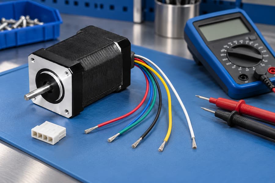
Prepare the motor for electrical inspection
Lead identification begins with the motor completely disconnected from its driver and other external circuits. Switch off the power supply, isolate the equipment, and follow the applicable discharge procedure before touching the wiring.
Never measure winding resistance while the motor is energized. Connected drive electronics can also distort resistance readings, so disconnect the motor leads from the driver before testing.
Use a suitable multimeter on its resistance setting. Check the meter and test leads first, then record the measurements systematically rather than relying on memory or cable appearance.
Identify winding pairs on a four-wire motor
For a conventional four-wire, two-phase motor, measure the resistance between candidate lead pairs. The two ends of the same winding should show continuity, while leads from separate isolated phases should normally show no continuity.
- First phase: Record the two leads that form one continuous winding path.
- Second phase: Identify the remaining pair and verify its continuity independently.
- Cross-pair checks: Measure between the two identified phases to check for unintended continuity.
- Documentation: Label each verified pair using neutral identifiers, such as Phase A and Phase B, until the manufacturer’s terminal designations are confirmed.
Do not assign phase identity from connector order, cable position, or insulation color alone. Incorrect pairing can prevent normal rotation and may produce vibration, weak torque, or unexpected current behavior.
Identify center taps on a six-wire motor
A conventional six-wire motor has three accessible leads for each phase. Resistance measurements can distinguish the center tap from the two outer ends when the winding arrangement is known.
- Center-tap candidate: Measure its resistance to the other two leads in the same phase group.
- Half-winding paths: The center tap should show continuity to both outer ends, with each measurement representing one winding section.
- Outer-to-outer path: Measuring between the two outer ends should cover the complete phase winding.
- Phase separation: Leads belonging to different isolated phases should normally show no continuity between them.
For a symmetrical winding, the two center-tap-to-end resistance readings are generally similar, while the outer-to-outer reading is approximately their sum. Treat this as a diagnostic pattern, not a universal acceptance tolerance.
Manufacturing tolerances, measurement resolution, contact resistance, and winding construction can affect the readings. If the results are inconsistent with the documented circuit, stop and investigate instead of assigning leads by guesswork.
Confirm findings against manufacturer documentation
A continuity test identifies electrical relationships, but it does not establish the correct supply voltage, operating current, connector pinout, or approved driver mode. Those details require authoritative motor documentation.
Compare the measured resistance pattern with the manufacturer’s winding diagram and terminal designations. If available documentation does not identify the center tap or connection ratings clearly, request confirmation before proceeding.
Maintain a lead-identification record containing the motor’s exact part designation, connector reference, measured winding relationships, and verified terminal assignments. This record provides a reliable basis for the subsequent wiring and commissioning checks.
Safe Wiring and Driver Commissioning
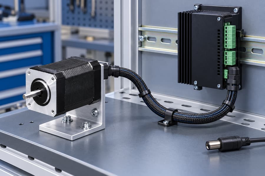
Verify the wiring before applying power
Complete all motor wiring changes with the driver power supply switched off and isolated. Allow the specified discharge time, then verify that the relevant electrical circuits have reached a safe state before handling connections.
Do not rely solely on a disabled motor command or an extinguished indicator light. Follow the driver’s documented isolation procedure and verify the supply condition using an appropriate measuring instrument where required.
Inspect each terminal against the approved wiring diagram. Confirm that the phase pairs, center taps, unused outer ends, and protective insulation match the selected four-wire or six-wire configuration.
- Four-wire bipolar: Connect each verified phase pair to its designated driver output.
- Six-wire full winding: Connect both outer ends of each phase and isolate its center tap.
- Six-wire half winding: Connect the center tap and one outer end per phase, isolating the other outer end.
- Unipolar operation: Connect the center taps and switched winding ends according to the approved driver circuit.
Check that disconnected leads cannot touch one another, grounded metalwork, or exposed terminals. Use suitable insulation and secure the leads so that vibration cannot gradually move them into contact with adjacent connections.
Set the driver current and operating mode
Configure the driver only after confirming the motor’s approved connection and corresponding current rating. Do not transfer a current setting from another motor or winding configuration without verifying its applicability.
Driver documentation may specify current as a peak value, an RMS value, or another defined quantity.
The motor documentation may use a different convention, so establish that both ratings refer to compatible quantities before setting the limit.
Never assume a universal conversion factor between full-winding and half-winding operation. Use the manufacturer’s stated rating for the selected configuration and follow the driver’s instructions for interpreting its current adjustment.
Verify the drive mode, supply voltage, microstepping setting, and other relevant parameters against the application requirements. These settings affect electrical operation and motion behavior, even when the motor’s physical connections are correct.
Secure cables and inspect the assembly
Cable routing deserves the same attention as terminal assignment. Provide strain relief near the motor and control cabinet, preventing connector pins from carrying the mechanical load of a moving cable.
Maintain suitable clearance from sharp edges, hot surfaces, moving mechanisms, and sources of electrical interference. Where cables flex during operation, check that the bend radius and cable construction suit the actual movement.
Inspect connector locking features and terminal retention before startup. Loose contacts can interrupt phase current, generate inconsistent motion, or produce localized heating that a brief initial test may not reveal.
Test unloaded, then under representative load
Begin with a controlled, unloaded test where the machine design permits it. Confirm that the motor starts correctly, rotates in the expected direction, and responds consistently to commands at conservative operating settings.
Listen for unusual noise and observe vibration, irregular stepping, and unexpected movement. If the motor stalls, loses synchronization, or behaves inconsistently, stop and investigate the wiring, current settings, drive mode, and mechanical arrangement.
After the unloaded checks pass, introduce a representative operating load. Test the actual motion profile, including relevant acceleration, deceleration, travel, holding periods, and repeated positioning cycles.
Check performance across the intended operating conditions rather than accepting one successful movement as proof of suitability. Record missed steps, positioning errors, abnormal vibration, and other deviations against the machine’s defined acceptance requirements.
Monitor temperature against documented limits
Temperature assessment should cover the motor, driver, connectors, and relevant cable sections during representative operation. Allow sufficient running time for thermal behavior to become meaningful for the intended duty cycle.
Use the manufacturer’s specified temperature limits and measurement method. Motor surface temperature does not directly establish winding temperature unless the documentation provides a valid relationship or measurement procedure.
If any component exceeds its applicable limit, or heating continues unexpectedly, stop the test and investigate. Possible causes include incorrect current settings, unsuitable winding connections, inadequate cooling, excessive mechanical load, or poor electrical contact.
| Commissioning check | Verification method | Acceptance basis |
| Electrical isolation | Verify power isolation and required discharge | Safe condition confirmed |
| Lead connections | Compare terminals with approved diagram | Every lead correctly assigned |
| Current configuration | Check motor rating and driver convention | Settings match approved limits |
| Cable security | Inspect terminals, connectors, and strain relief | No loose or exposed connections |
| Unloaded motion | Test direction, smoothness, and command response | Meets defined motion requirements |
| Loaded operation | Run representative motion cycles | Meets application acceptance criteria |
| Temperature | Measure using the specified method | All components remain within documented limits |
Selecting and Documenting the Right Configuration
Match the wiring to the application
Select the connection according to the motor’s approved electrical configurations and the driver’s capabilities, not simply the number of available terminals.
Confirm the required speed, torque, duty cycle, and operating environment before choosing between full-winding and half-winding operation.
Consider the complete electrical system, including supply voltage, driver current regulation, cable length, connector ratings, and installation constraints. A connection that is electrically permissible may still require further testing to establish satisfactory loaded performance.
If the required operating point cannot be achieved within documented limits, reassess the motor, driver, mechanical load, and motion profile. Do not compensate for an unsuitable configuration by exceeding the permitted winding current.
Record the approved wiring and settings
Prepare a wiring record that another technician can use without reconstructing the original inspection. Include the motor identification, connector reference, verified phase assignments, and a diagram showing every connected and isolated lead.
- Motor details: Record the exact motor designation and the applicable manufacturer documentation revision.
- Connection method: Identify four-wire bipolar, six-wire full-winding, six-wire half-winding, or approved unipolar operation.
- Current settings: Record the selected driver value, its peak or RMS convention, and the corresponding motor rating.
- Driver configuration: Document the driver identification, supply voltage, operating mode, microstepping settings, and relevant motion parameters.
- Test results: Record unloaded and representative-load results, observed temperatures, deviations, and corrective actions.
- Acceptance approval: Identify the applicable acceptance criteria, test date, and responsible reviewer.
Keep the wiring diagram consistent with the installed hardware.
If a connector, driver, motor, or winding configuration changes, review the electrical compatibility and repeat the affected verification and acceptance tests before returning the machine to service.
The completed wiring and acceptance record should identify the approved lead connections, isolated terminals, driver settings, measurement methods, and demonstrated operating conditions, providing a traceable reference for maintenance and future modifications.