
An axial flux motor’s short axial dimension is only one part of its installation envelope. The equipment designer must also allow for diameter, mounting structure, coupling, guards, cables, cooling connections, and the space needed to inspect or remove the motor. Packaging should be approved against the assembled machine and its service tasks, not against an isolated motor outline.
Which Surrounding Machine Components Can Obstruct an Otherwise Compact Axial Flux Motor?
A disc-shaped motor can reduce space in one direction while creating constraints in another. Nearby frame members, pipework, or access panels may conflict with the larger radial envelope or with connectors around the housing. Evaluate the motor together with the surrounding frame and service connections, then check that technicians can still perform the planned inspection and replacement tasks.
Start with the selected model from the Leili axial flux motor range and obtain the relevant installation drawing. Product-family illustrations explain the general form but should not be used as dimensional release documents. Confirm the drawing revision and any options that change external connections or mounting details.
Keep the packaging objective explicit. A project may prioritize reduced machine length, a lower mass, improved service access, or a different mounting arrangement. Those objectives can conflict, so a clear priority helps the design team judge whether a proposed layout delivers the intended benefit.
Which Boundaries Should the Layout Drawing Show?
Show the physical motor, the operating clearance around it, and the service space required for planned tasks as distinct boundaries. These boundaries answer different questions and should not be merged into one vague clearance allowance. A component can fit physically while leaving no practical route for tools, connectors, or removal.
Include the coupling and guard as actual geometry where available. The motor’s axial advantage can be partly consumed by the transmission interface, sensor arrangement, or a required guard. Leili’s article on axial flux motor integration with gearboxes and direct-drive systems provides related system context, while the layout needs the chosen interface dimensions.
| Envelope | Items Included | Review Question |
| Physical | Housing, feet, connectors | Does the assembly fit? |
| Operating | Cooling and movement clearances | Can it operate as specified? |
| Connection | Cables, hoses, fittings | Can connections be routed correctly? |
| Service | Tools and inspection access | Can routine work be performed? |
| Removal | Lifting and withdrawal route | Can the motor be replaced? |
Dimension these boundaries from defined references on the machine. An installer should be able to locate the motor and check a potential conflict without interpreting a presentation rendering. Where a boundary depends on supplier instructions, cite the relevant drawing or installation requirement in the design record.
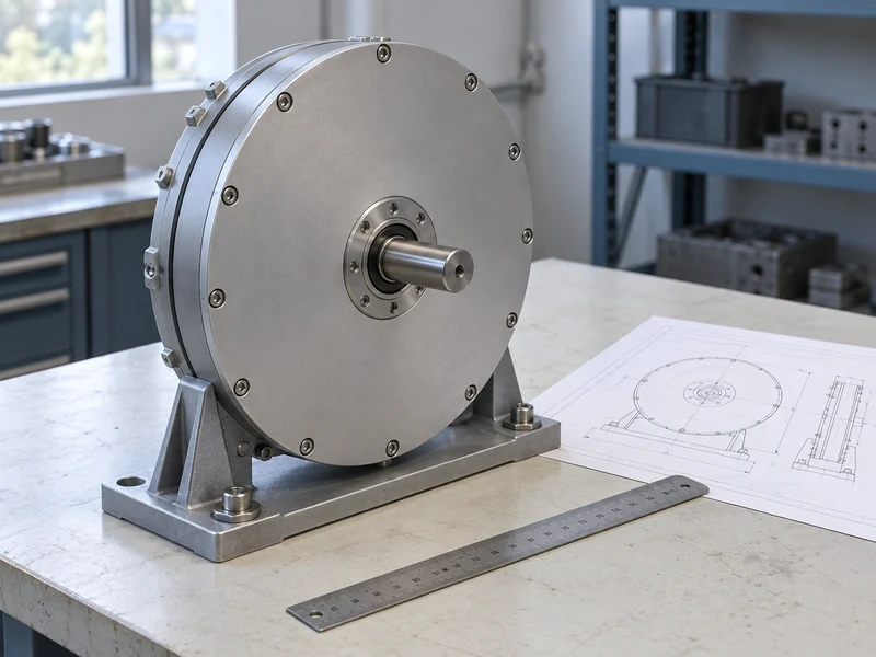
How Much Space Do Cables and Cooling Connections Need?
Connection space depends on the actual cable, connector, hose, and fitting arrangement. Allow for permitted bend geometry, strain relief, assembly access, and movement or vibration where relevant. Do not invent a universal clearance from a photograph of another installation.
A connector may be accessible before assembly but obstructed after surrounding panels or pipes are installed. Review the assembly sequence as well as the finished layout. The design should identify whether a connection can be inspected and replaced without removing unrelated equipment.
Cooling connections deserve special attention when selecting a liquid-cooled arrangement. Hose routing, fittings, isolation provisions, and the location of associated equipment can affect the complete package. Leili’s guide to axial flux motor cooling methods explains the broader cooling choices; the project drawing must show the actual selected circuit interfaces.
Why Should Mounting Loads Be Reviewed with the Envelope?
Packaging decisions change where the motor is supported and how loads enter the machine structure. A compact arrangement is not automatically a sufficiently stiff or properly aligned arrangement. Confirm the permitted orientation, mounting interfaces, and support requirements with the motor supplier and machine designer.
An adapter can solve a dimensional mismatch while introducing another tolerance stack or a less rigid load path. Include its thickness, locating features, and assembly method in the review. Treat the adapter as an engineered component rather than an invisible part of the installation allowance.
Different axial flux constructions can have different integration implications. Leili’s comparison of single-rotor and dual-rotor axial flux designs provides background, but the selected assembly’s mounting instructions govern the project. Do not infer permissible external loads from a general topology description.
How Should Tolerances Be Included in a Clearance Check?
Use the worst credible dimensional combination for clearances that could affect assembly or operation. Nominal dimensions alone may show a comfortable gap that disappears when manufacturing and installation tolerances are included. For each critical gap, mark the locating features that determine its size and specify the conditions under which those dimensions are checked.
NIST’s discussion of dimensional traceability notes that measurement uncertainty and thermal expansion matter to dimensional results. For a layout review, the engineering implication is to state relevant tolerances and measurement conditions rather than treating every measured dimension as exact. The motor supplier must provide the actual permissible interface limits.
Do not add unrelated tolerances mechanically without understanding the locating scheme. Some features are controlled by a common datum, while others contribute independently to the assembled position. A drawing review with the machine designer can prevent both an optimistic clearance and an unnecessarily large allowance.
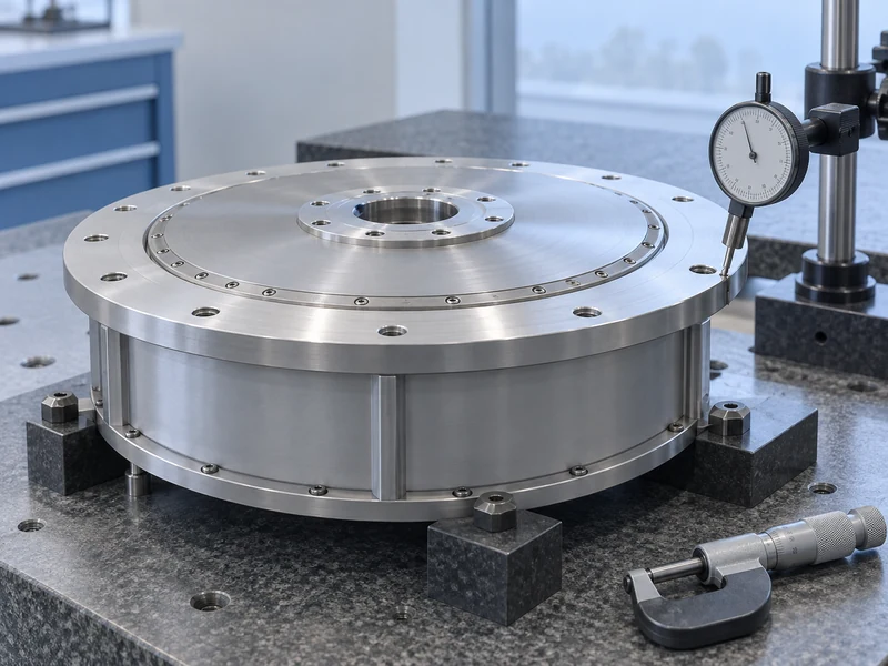
What Service Tasks Should Be Rehearsed Before Design Release?
Walk through inspection, connection access, coupling access, and replacement using the proposed layout. Identify the tools and lifting arrangement required by the approved service method. Rehearsing these tasks on a layout model or mock-up can expose a blocked tool path that a general arrangement view fails to make obvious.
Consider the sequence in which surrounding components must be removed. If a routine motor replacement requires disturbing a critical pipe or an unrelated precision assembly, the maintenance cost may offset part of the packaging benefit. The design team can then decide whether a different orientation or removable panel is worthwhile.
Keep lifting and handling requirements tied to the manufacturer’s instructions. A convenient-looking housing feature is not automatically a lifting point. The layout should provide room for the approved handling method without relying on an improvised route through the assembled machine.
How Can Candidate Models Be Compared Fairly?
Compare the installed package under the same boundary and duty requirements. Include necessary adapters, cooling equipment, connection space, and guards when those items differ between candidates. A motor-only volume comparison can be useful as preliminary information but does not establish the final machine footprint.
The published Leili 30 kW axial flux motor page lists multiple variants with different speed and cooling arrangements. This illustrates why a shared power label is not enough to choose an installation drawing. Identify the exact candidate and confirm its dimensions and interface details before calculating a packaging advantage.
Use a comparison sheet that records both the measured or drawing-based dimensions and the remaining assumptions. An unresolved connector orientation or service requirement should appear as an open item. Keeping those gaps visible prevents a footprint-reduction calculation from appearing settled while connector positions or removal clearances are still unknown.
How Can a Simple Layout Trial Expose a Hidden Conflict?
Consider a hypothetical machine in which the motor body fits between two frame members, but its coolant fitting faces one of those members. Rotating the motor might improve hose access while moving the electrical connection into the path needed to remove the guard. The correct response is to compare complete orientations, including assembly and service requirements, rather than approve the first body position that fits.
Create a short task sequence for each candidate orientation: install the motor, connect services, fit the guard, inspect connections, and remove the unit. Mark the components that must move during each task and check whether that movement is permitted in the finished machine. This exercise can be performed before detailed manufacturing drawings are complete, provided the unresolved dimensions remain identified.
The resulting decision should explain which orientation was selected and why. If one option is shorter but requires substantial dismantling for replacement, record that tradeoff for the project owner. Packaging approval then reflects the equipment’s practical use instead of rewarding the smallest isolated outline.
What Should the Final Packaging Approval Contain?
The approval should identify the exact motor configuration, controlled drawings, connection routes, mounting arrangement, and required service clearances. Include a record of interference checks and any conditions that must be preserved during detailed design. Assign ownership of unresolved interfaces before releasing the machine for manufacture.
When the supplier changes an option or drawing revision, review whether the installation envelope changes. A small connector or fitting revision can matter in a tightly packaged machine even when the motor’s main dimensions remain unchanged. Attach the approval to the selected variant, connection options, and drawing revision so that a later family-level substitution cannot silently alter the reviewed package.
A useful axial flux packaging result is a machine that is compact, operable, and maintainable under its intended conditions. Measuring only motor length captures one possible advantage but leaves the integration work unfinished. Reviewing the complete envelope makes that advantage concrete and gives the installation team a design they can actually build.