
An axial flux motor integration review should assign responsibility for transmitted torque, external shaft loads, coupling selection, alignment, and the supporting structure. Motor power and shaft diameter do not establish the permissible loads from a pulley, gear, impeller, or other attached component. The motor supplier and machine designer should approve the complete mechanical arrangement before the interface is released.
Why Is Torque Only Part of the Interface Review?
Torque describes the rotational load transmitted through the shaft, but an attached component can also impose radial or axial forces and bending moments. Their effects depend on the load magnitude, direction, location, and operating pattern. A motor selected correctly for power can still be unsuitable for an unreviewed external load arrangement.
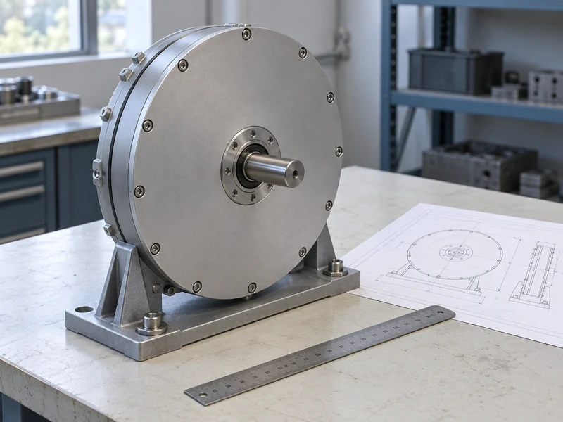
When considering Leili axial flux motors, describe how the driven equipment connects to the motor. Include drawings showing the relevant component locations and support points. A statement that the motor drives a pump or another machine does not explain which loads reach its bearings.
The enquiry should identify whether the driven equipment has its own bearings or relies on a shared support arrangement. These configurations can impose very different responsibilities on the motor. Resolve that distinction before treating a direct connection as a simple packaging choice.
Which Loads Should the Machine Designer Supply?
The machine designer should supply the expected torque and any external forces or moments at the motor interface across the required operating states. Include normal operation, acceleration, deceleration, and other permitted transient conditions where relevant. State the direction and point of application rather than giving an isolated force value.
A radial load applied farther from a support can have a different bending effect from the same load applied closer to it. The supplier therefore needs the actual geometry, not only the force magnitude. If the design includes a pulley or gear, identify its location and the associated load assumptions explicitly.
| Interface Item | Information Required | Primary Review Owner |
| Transmitted torque | Magnitude, speed, duty | Machine designer and motor supplier |
| External forces | Direction and application point | Machine designer |
| Permitted shaft loads | Limits for selected configuration | Motor supplier |
| Coupling | Rating and installation requirements | Coupling supplier and integrator |
| Support structure | Stiffness and locating arrangement | Machine designer |
When an input is uncertain, provide a justified range and explain its origin. The supplier can then identify whether further analysis or measurement is needed. An unsupported exact value creates false confidence and can make later responsibility harder to establish.
How Should a Coupling Be Selected and Documented?
The coupling should be selected for the actual torque, speed, transient duty, shaft interfaces, and installation conditions. Its ability to accommodate a stated misalignment does not remove the need for proper machine alignment. Follow the coupling manufacturer’s application and installation requirements for the selected arrangement.
Check the hub geometry, shaft engagement, locating method, and available assembly space against approved drawings. Include guarding and access for inspection or replacement in the layout. A coupling that meets a torque requirement can still create a packaging or service problem if those interfaces are omitted.
Leili’s guide to axial flux motor integration with gearboxes and direct-drive systems provides broad integration context. This review addresses the mechanical details after the overall arrangement is chosen. Before approving the connection, place the selected coupling’s requirements beside the motor interface drawing and the driven machine’s load cases, and resolve any disagreement among them.
What Should Be Confirmed About Bearings and External Loads?
Send the proposed shaft loading and its application point to the motor manufacturer, asking for confirmation against the selected bearing arrangement and duty. Clarify whether limits depend on speed, load position, duty, or another stated factor. Do not infer bearing capacity from the external motor diameter or from the axial flux topology.
The internal magnetic arrangement and external machine loads are separate parts of the design assessment. Leili’s comparison of single-rotor and dual-rotor axial flux motors explains structural alternatives, but does not establish a universal allowance for an attached machine. Supplier confirmation should address the actual external load case.
If the proposed arrangement exceeds or falls outside the available data, request an engineered assessment or revise the support concept. Adding an independent bearing or changing the transmission can alter the load path, but those changes also need design review. Treat them as explicit design decisions rather than informal installation fixes.
How Should Alignment Be Defined for the Assembled Machine?
Alignment should be defined using the approved reference features, measurement method, and limits for the complete assembly. The motor, coupling, and driven equipment may each contribute requirements. Agree how those requirements will be reconciled before installation begins.
Temperature and support conditions can influence the relationship between connected components. NIST’s guidance on dimensional traceability identifies thermal effects and uncertainty as relevant to dimensional measurement. For the machine, define the inspection conditions and ask the responsible designers how operating changes are addressed rather than assuming a cold reading answers every question.
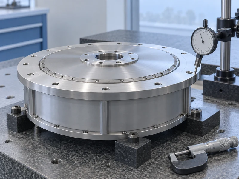
Record the reference condition after acceptance. If a later symptom prompts realignment, the original record helps establish what changed. It is particularly useful when maintenance work has disturbed mounting parts or when the operating temperature differs from the original duty.
What Role Does the Support Structure Play?
The structure locates the components and carries their loads, so it is part of the motor integration even when supplied by another organization. Review mounting surfaces, adapters, stiffness, and the intended load path. A geometrically compatible arrangement may still be unsuitable if its support behavior has not been considered.
The disc form can influence packaging choices, but it does not guarantee that a thin adapter or a convenient mounting bracket is adequate. The machine designer should assess the actual geometry and forces. Record the assumed bracket geometry, support behavior, and force path with the design approval; these details identify what must be reconsidered when the mounting structure changes.
Leili’s explanation of the axial flux motor manufacturing process provides background on controlled motor production. The completed machine still depends on the quality and accuracy of its mating components. Incoming motor inspection cannot substitute for checking the support and adapter supplied by the integrator.
Which Operating Transitions Need Mechanical Review?
Include starts, stops, reversals where permitted, and process disturbances that materially change interface loads. A steady torque value can hide a transient demand important to coupling or shaft assessment. The event frequency and duration should be part of the description.
Do not assume that every protective electrical trip creates a mechanically acceptable stopping condition. The machine’s behavior depends on its inertia, load, and control arrangement. The integrator should coordinate the mechanical and electrical reviews so that the permitted operating sequences are consistent.
For a candidate on the Leili 30 kW axial flux motor page, identify the exact rated speed and model before assessing the transmission. The same power at another speed changes the torque associated with that operating point. Published power alone is therefore insufficient for selecting the coupling or validating an external load.
How Can a Late Transmission Change Alter the Approval?
Consider a hypothetical machine initially designed with a supported driven shaft and a flexible coupling. Replacing that arrangement with a pulley mounted directly on the motor shaft introduces a different external-load question, even if required shaft power remains unchanged. The earlier torque approval does not automatically cover the new geometry.
The designer should provide the revised forces, application point, speed, and duty to the motor supplier. The coupling or transmission supplier must also review the selected components under their applicable requirements. Update the associated guard, mounting details, and maintenance clearances alongside the transmission drawing, so the revised pulley arrangement is assessed as a complete installation.
This example shows why interface approval must follow the assembled configuration rather than the motor’s power label. A change that appears minor in a purchasing description can move load responsibility to a different bearing or support. Keeping the drawing and load assessment linked helps the project identify that change before installation.
What Should the Interface Approval Package Contain?
The package should include the load cases, controlled drawings, coupling specification, supplier confirmations, alignment requirements, and acceptance plan. Identify the owner of each interface and any unresolved assumptions. Approval should refer to the complete configuration rather than a collection of independently acceptable components.
During commissioning, verify representative operation and preserve observations relevant to vibration, temperature, and mechanical behavior. Use the approved test procedure and investigate unexplained differences before changing several variables. The goal is to confirm the assembled system against the agreed design basis.
Retain the package for future replacement and process changes. A new coupling, added pulley, different speed, or altered support can change the original load assessment even when the motor remains the same. Clear ownership of shaft-load and coupling checks makes those changes reviewable and helps protect the benefits of axial flux integration.