
A repetitive stepper mechanism accumulates wear through starts, reversals, loaded motion, and dwell periods. A useful test reproduces those interactions instead of running the gearbox continuously.
The protocol should measure baseline output lost motion, monitor operating conditions, and set functional limits before endurance begins. Results require documented fixture effects, measurement uncertainty, and representative duty.
What Must a Gear Wear Test Prove?
Define the test objective
Start by deciding whether the test must verify functional endurance, characterize wear progression, or investigate a suspected failure. These objectives require different measurements and different stopping rules.
A functional endurance test asks whether the mechanism continues meeting application requirements after repeated operation. A characterization study instead tracks how measurable performance and physical condition change over time.
Define the test boundary before selecting equipment. It may include the stepper motor, gearbox, drive settings, couplings, output bearings, mounting structure, and applied load; record every component that can affect results.
Gear wear is not identical to functional failure. Tooth-surface damage may develop while the mechanism still performs acceptably, whereas rising lost motion or missed output movement can violate requirements before severe damage is visible.
Set acceptance criteria before running the test. Identify the measurements that determine pass or fail, the diagnostic observations used to explain changes, and the conditions that require an immediate stop.
Choose a geared stepper motor configuration that matches the intended assembly and operating envelope. A different ratio, lubricant, mounting arrangement, or load may not represent the target mechanism.
How Should the Duty Cycle Represent Real Operation?
Reproduce the motion sequence
Build the test cycle from the actual machine sequence, including commanded travel, step count, speed, acceleration, deceleration, starts, stops, and direction changes. Record the source for each condition.
Reversal frequency deserves specific attention because alternating torque can repeatedly load opposite tooth flanks. A one-direction rotation test may miss wear behavior associated with backlash take-up and reversing loads.
Include dwell periods and define what happens during each pause. Powered holding, reduced-current holding, and unpowered rest can create different thermal and mechanical conditions, so they should not be treated as interchangeable.
Specify load, lubrication, and environment
Describe output torque during movement, acceleration, reversal, and holding. Also document load inertia, external forces, and relevant radial or axial shaft loads, because these affect tooth contact and bearing behavior.
Record lubricant type, lubrication method, initial condition, and any scheduled replenishment. If the purpose is to represent normal service, maintenance actions during testing should follow the intended maintenance procedure.
Define ambient temperature, contamination exposure, mounting orientation, and other environmental variables relevant to the installation. Keep the test within supplier-approved limits rather than inventing load, speed, or temperature ratings.
Make the cycle reproducible
Write the duty cycle as a controlled sequence that another engineer can implement without interpreting vague labels such as “normal load” or “frequent reversal.” Document commanded and measured conditions separately.
Table 1: Representative Duty-Cycle Definition
| Duty variable | Application evidence | Test representation | Required record |
| Motion profile | Machine sequence or controller settings | Travel, speed, acceleration, and deceleration | Commanded and measured motion |
| Reversals and dwell | Operating sequence | Direction changes and pause states | Reversal count and dwell duration |
| Output load | Measured or specified load conditions | Representative torque and external forces | Load profile and setup |
| Lubrication | Approved lubricant and service method | Defined initial and maintenance condition | Lubricant identification and actions |
| Environment | Installation requirements | Relevant temperature and contamination conditions | Sensor locations and environmental log |
A cycle counter should use a clear definition of one completed cycle, including whether partial sequences or aborted movements count. This convention must remain unchanged throughout the test.
How Should Baseline Output Lost Motion Be Measured?
Establish a repeatable method
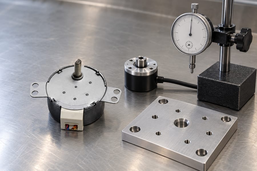
Measure output lost motion before endurance using a documented fixture, reference position, applied torque, measurement direction, and temperature condition. Repeat the procedure so baseline variation is known.
During a controlled reversal, apply torque in one direction and then the opposite direction while measuring output angular displacement. Use a consistent loading procedure and avoid abrupt impacts that distort the result.
Record instrument resolution, calibration status, measurement geometry, and repeatability. Preserve raw readings and photographs of the setup so later changes can be compared against the original condition.
Separate clearance from elastic deflection
Measured reversal displacement can combine tooth clearance with elastic deformation, bearing movement, coupling compliance, and fixture flexibility. Therefore, total lost motion should not automatically be reported as gear-tooth backlash.
Where practical, measure displacement across an appropriate range of applied torque. A clearance-related deadband and load-dependent deflection may respond differently as torque changes, helping separate their contributions.
Characterize fixture and coupling compliance independently when feasible. If they cannot be isolated reliably, state that limitation and report the result as system-level output lost motion rather than claiming a gearbox-only measurement.
Preserve comparability over time
At each later inspection, repeat the baseline method with the same torque conditions, reference points, mounting, and temperature controls. Note any unavoidable deviations before comparing results.
Interpret small changes in relation to measurement uncertainty and baseline repeatability. A difference that falls within normal measurement variation should not be presented as confirmed wear without supporting evidence.
How Should the Test Fixture, Instrumentation, and Safety Be Designed?
Reproduce the installed mechanical arrangement
Build the fixture around the intended mounting geometry, shaft supports, coupling, and load direction. Differences in alignment or restraint can introduce forces that distort wear results.
Check shaft alignment and coupling installation before endurance testing. Unintended bending loads, loose fasteners, or fixture resonance can cause damage unrelated to normal gear engagement.
The load system should reproduce the application within supplier-approved limits. Document how torque is applied, how the output is supported, and whether the fixture adds friction or compliance.
Guard rotating parts and contain possible fragments or lubricant release. Arrange inspection access so routine checks do not require unsafe reach-in work or unnecessary movement of the assembly.
Verify sensors and protective measures
Select instrumentation suited to each measured variable and operating range. Sensors must not materially alter the mechanism’s load, stiffness, or thermal behavior.
Place temperature probes at defined locations, such as the gearbox housing or motor body, and keep positions consistent. Comparable readings require stable sensor placement and contact conditions.
Before operation, verify calibration status, signal logging, emergency stopping, over-temperature response, and safe electrical isolation. Define restart authorization and required checks after a protective stop.
Document motor, drive, and control settings throughout testing. The stepper motor and its drive current, pulse commands, and acceleration profile affect heating and dynamic load, so record every change.
What Should Be Counted and Monitored During Endurance?
Track cycles and interruptions
Use a cycle counter with a written definition of completion. Specify whether a cycle includes both travel directions or a return to a defined reference position.
Record cumulative cycles and operating hours alongside starts, reversals, pauses, and aborted sequences. Do not count incomplete movement as successful completion simply because the controller issued a command.
Maintain an event log for power interruptions, emergency stops, maintenance, sensor faults, and manual interventions. These events may change temperature, lubrication, or loading history and should remain visible during analysis.
Monitor load and temperature trends
Record output torque or another justified load indicator during representative cycle phases. If continuous measurement is impractical, define repeatable checkpoints and state which operating periods are not captured.
Trend temperatures at the same sensor locations under comparable cycle conditions. A temperature increase may indicate friction or changing conditions, but cannot identify a specific wear mechanism alone.
Synchronize sensor data with cycle counts and event timestamps. This helps determine whether changes developed gradually, followed a particular load sequence, or began after an interruption.
Respond consistently to abnormal behavior
Predefine responses to stalls, missed steps, unusual noise, torque excursions, or temperatures outside the approved envelope. Depending on the event, the procedure may require a controlled stop and inspection.
Preserve data immediately before and after abnormal events. Restarting without documenting the cause can obscure developing failure and make comparisons unreliable.
When Should Inspections and Measurements Occur?
Set inspection intervals before testing
Plan inspection points by accumulated cycles, elapsed operating time, or both. Choose intervals based on duty, expected rate of change, supplier guidance, and measurement sensitivity.
Use the same interval scheme across comparable samples unless a documented event justifies an additional inspection. Trigger extra checks after overheating, unexpected noise, abnormal torque trends, or significant interruptions.
Repeat checks without changing the evidence
At each checkpoint, repeat functional measurements using the established procedure and record operating conditions. Compare results with baseline variation before deciding whether a change is meaningful.
Inspect external surfaces and accessible components before disassembly. Disassembly can disturb alignment, redistribute lubricant, or introduce handling marks, so document the as-tested condition first.
Standardize photography, cleaning, debris collection, and component handling. If lubricant is sampled or replenished, document the amount and method because inspection may otherwise change test conditions.
Which Wear Modes and Debris Should the Inspection Distinguish?
Identify surface damage carefully
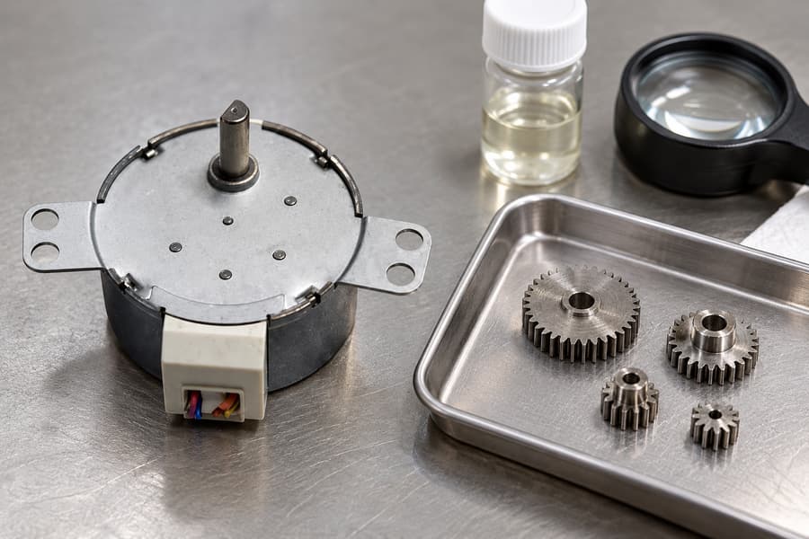
Pitting appears as localized surface cavities or material loss on gear teeth. Record its location, distribution, and progression without inferring its cause from appearance alone.
Abrasive wear may produce scoring, grooves, or material removal when hard particles or rough surfaces cut across tooth flanks. Document visible contamination and related lubricant findings.
Adhesive wear can appear as smearing, scuffing, or material transfer where contacting surfaces locally adhere and separate. Record affected tooth regions and operating history, because load, lubrication, and temperature may influence damage.
Examine lubricant and debris
Collect debris consistently and record its appearance, approximate quantity, and location. Distinguish fine particles from larger fragments that could indicate more substantial component damage.
Note lubricant discoloration, contamination, unusual consistency, or visible particles, but treat these as supporting observations rather than definitive proof of a failure mode. Preserve representative samples when further examination is warranted.
Compare photographs, debris records, and component condition across inspection intervals. A defensible interpretation connects observed changes with measured operating history instead of relying on one visual symptom.
How Should Functional Failure and Test Completion Be Defined?
Set acceptance criteria before endurance begins
Define failure limits before testing, using application requirements and approved component specifications. Avoid universal thresholds that ignore load, positioning needs, and duty-cycle differences.
Specify allowable output lost motion, positioning repeatability, torque transmission, temperature, and successful cycle completion where each matters. State the measurement method and conditions attached to every limit.
Separate functional failure from visible wear. Surface damage may not immediately prevent operation, while missed steps, unstable positioning, or insufficient output torque can cause failure before extensive damage appears.
Define whether one breached criterion ends the test or triggers a controlled pause and investigation. Establish safety-related stop rules independently of performance acceptance criteria.
Decide when a specimen has completed the test
Set the required cycle count, operating duration, inspection checkpoints, or failure endpoint before starting. Record the rule used to classify each specimen’s outcome.
A specimen that reaches the planned endpoint without breaching its criteria has completed that test exposure; this does not establish unlimited service life or prove population-wide reliability.
Plan samples and account for uncertainty
Choose the number of specimens according to the study objective, expected variability, resources, and required confidence.
Explain the basis for the sample size and avoid extending results from a single tested unit to the entire production population.
Record component identification, assembly procedures, and sample-specific deviations that could explain different outcomes.
Compare measured changes with instrument uncertainty and baseline repeatability. When a result approaches an acceptance boundary, consider uncertainty before declaring a pass or failure, and repeat measurements only under a defined procedure.
Record all specimens, including early failures, withdrawn samples, and interrupted runs. If a run ends without the failure being investigated, report its exposure and reason for termination rather than counting it as successful.
A run stopped at the planned endpoint without observed failure is commonly treated as a right-censored observation in life analysis.
An unrelated fixture failure or procedural interruption needs separate classification because it may not represent service life.
When Is Accelerated Gear Wear Testing Valid?
Check whether acceleration preserves the failure mechanism
Increasing speed, load, reversal frequency, or temperature can shorten a test, but may also change how damage develops. Do not assume a proportional relationship between test duration and service life.
Higher speed can alter lubricant film behavior, heat generation, and debris movement. Greater load can change tooth contact stress, shaft deflection, bearing reactions, and the balance between surface and structural damage.
Changing reversal frequency or dwell time can alter lubrication distribution, thermal recovery, and load transitions per operating hour. These differences may produce a wear pattern unlike the intended application.
Validate accelerated conditions
Use representative duty as a reference and document every deliberate acceleration factor. Keep modified conditions within approved limits and obtain supplier approval before changing the operating envelope.
Compare damage location, morphology, debris, temperature history, and functional deterioration between accelerated and representative-condition samples where practical. Similar appearance alone does not prove equivalent failure mechanisms, but major differences warn against direct lifetime extrapolation.
Use acceleration only when there is a defensible technical basis connecting the modified test to intended service. If that relationship remains uncertain, report the test as comparative or exploratory rather than claiming a service-life prediction.
What Evidence Should the Final Test Report Contain?
Preserve the test configuration and results
Identify each specimen and record relevant drawings, revisions, gear ratio, lubricant, assembly details, motor and drive settings, fixture configuration, and approved operating limits. This makes later comparisons meaningful.
Include the duty-cycle definition, cycle-counter logs, operating hours, reversal counts, torque records, temperature trends, interruptions, and maintenance actions. Preserve time references so operating changes can be aligned with inspection findings.
Report baseline and subsequent lost-motion results using consistent units and conditions. Explain fixture compliance, measurement uncertainty, and method deviations that limit direct comparison.
Summarize acceptance and wear evidence
Include inspection photographs, observed damage locations, debris and lubricant findings, and the reasoning behind any proposed wear mechanism. Distinguish direct observations from interpretations.
Table 2: Endurance Test Results and Acceptance Record
| Evaluation item | Evidence to retain | Acceptance basis |
| Cycle completion | Counter log and interruptions | Predefined exposure target |
| Output lost motion | Baseline and interval measurements | Application-defined limit |
| Torque and temperature | Time-stamped monitoring records | Approved operating and functional limits |
| Wear and debris | Images, inspection notes, samples if needed | Predefined damage criteria |
| Uncertainty and deviations | Calibration, repeatability, method changes | Documented decision rule |
| Final specimen status | Completed, failed, withdrawn, or censored | Test protocol and reason for termination |
Report every specimen’s outcome and exposure, including tests that stopped early or ended without observed failure. State whether conclusions apply to functional acceptance, comparative wear behavior, or a justified life estimate.
Finish the report package with the approved procedure version, raw data location, calibration records, inspection history, deviations, and reviewer sign-off.
These records allow engineers and suppliers to verify the evidence behind test findings and subsequent technical decisions.